
X-ray source device

a source device and x-ray technology, applied in the manufacture of electrode assemblies, electrode systems, electrodes, etc., can solve the problems of carbon nanotubes being undesirably destructed or detached from substrates, gate may be undesirably attached to cathodes, etc., to achieve the effect of reducing the width of the insulation body

Inactive Publication Date: 2013-09-12
SAMSUNG ELECTRONICS CO LTD
View PDF10 Cites 15 Cited by
  • Summary
  • Abstract
  • Description
  • Claims
  • Application Information

AI Technical Summary

Benefits of technology

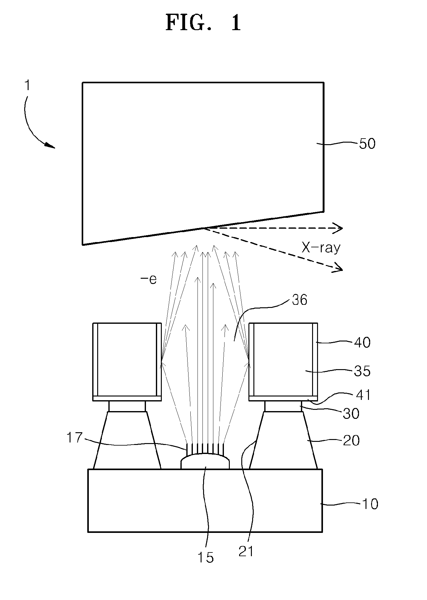
The patent describes a feature where the width of an insulation body decreases from one surface to another. This may provide technical benefits in certain applications.

Problems solved by technology

Since current flows beyond a current density limit in a portion of the carbon nanotube where the electric field is concentrated, the carbon nanotube may be undesirably destructed or detached from a substrate due to the high electric field.
Also, as a gate may be detached, the gate may be undesirably attached to the cathode due to the high electric field between the gate and the cathode.

Method used


Image

  • X-ray source device
  • X-ray source device
  • X-ray source device

Examples


Embodiment Construction

[0031]The present invention will now be described more fully with reference to the accompanying drawings, in which exemplary embodiments of the invention are shown. The invention may, however, be embodied in many different forms and should not be construed as being limited to the embodiments set forth herein; rather, these embodiments are provided so that this disclosure will be thorough and complete, and will fully convey the concept of the invention to those skilled in the art. In the drawings, the thicknesses of layers and regions are exaggerated for clarity.

[0032]It will also be understood that when a layer is referred to as being “on” another layer or substrate, it can be directly on the other layer or substrate, or intervening layers may also be present. Like reference numerals in the drawings denote like elements, and thus their description will be omitted. As used herein, the term “and / or” includes any and all combinations of one or more of the associated listed items.

[0033]...


PUM


Abstract

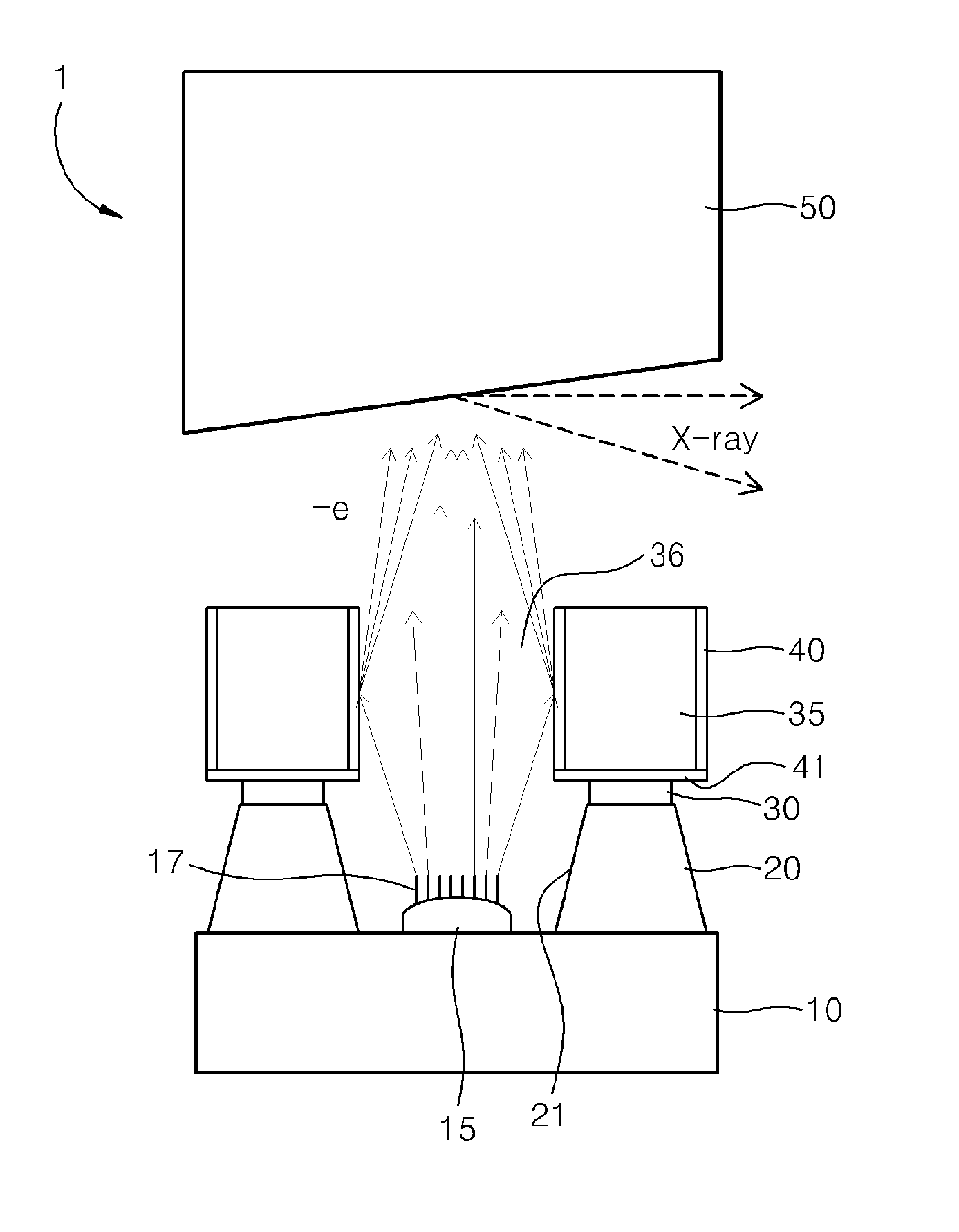
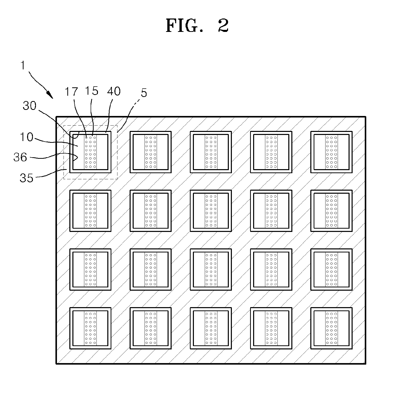
An X-ray source device includes a substrate, a cathode electrode on the substrate, an emitter on the cathode electrode, an insulation body around the cathode electrode, a gate electrode on the insulation body, a first secondary electron emission layer at a side wall of the gate electrode and emitting secondary electrons upon collision with an electron beam emitted by the emitter, and an anode electrode separated from the gate electrode.

Description

CROSS-REFERENCE TO RELATED APPLICATIONS[0001]This application claims priority to Korean Patent Application No. 10-2012-0022888, filed on Mar. 6, 2012, and all the benefits accruing therefrom under 35 U.S.C. §119, the disclosure of which is incorporated herein in its entirety by reference.BACKGROUND[0002]1. Field[0003]Provided is an X-ray source device capable of stably emitting electrons by amplifying them.[0004]2. Description of the Related Art[0005]With the constant increase in consumer health awareness, many studies have been performed on various pieces of medical equipment. An X-ray source device is an example of such medical equipment. Carbon nanotube is generally used for an emitter in an X-ray source device since an electron beam can be focused via a high emission current and a relatively simple structure. Also, since an on / off switching speed of an emitter using the carbon nanotube is fast, an X-ray source device including an emitter using the carbon nanotube has been active...

Claims


Application Information

Patent Timeline
Patent Type & Authority Applications(United States)
IPC IPC(8): H01J35/04H01J9/18
CPCH01J3/021H01J35/065H01J9/18H01J35/045H01J2235/068H01J35/08H01J2201/30469
Inventor JEONG, TAE-WONKIM, YONG-CHULKIM, DO-YOONKIM, IL-HWANPARK, SHANG-HYEUN
Owner SAMSUNG ELECTRONICS CO LTD
Learn More