Heat energy extraction system from underground in situ combustion of hydrocarbon reservoirs

a hydrocarbon reservoir and energy extraction technology, which is applied in the direction of heat storage fuel, dynamo-electric machines, other heat production devices, etc., can solve the problems of large environmental damage, high cost and sometimes ineffective processes, and serious environmental problems, and achieve the effect of improving the functioning and efficiency of the related circui

Active Publication Date: 2013-09-12
7238703 CANADA
View PDF7 Cites 11 Cited by
  • Summary
  • Abstract
  • Description
  • Claims
  • Application Information

AI Technical Summary

Benefits of technology

[0011]Where the heat source is a hydrocarbon reservoir undergoing in situ combustion, the in situ combustion usually requires one or more injection wells extending from the ground surface into the hydrocarbon reservoir for injecting a gas with oxidizing capability (an “oxidizing gas”) to support combustion of the hydrocarbons, which injection wells are in configurations that enhance the functioning and efficiency of the related circuits.

Problems solved by technology

It is generally accepted that serious environmental problems arise during the production of electric power using any of these hydrocarbon fuels, albeit some less than others.
Greenhouse gases are generated and released into the atmosphere, and many other contaminants are brought to the surface and must be dealt with using expensive and sometimes ineffective processes.
With each step in the processes of extracting, refining, transporting and ultimately burning any hydrocarbon for use in a distant power plant or car, considerable damage is done to the environment.
Each of these process steps is also expensive.
However, the prior systems do not avoid the problems of environmental contaminants being transported to the ground surface, or combustion gases being released into the atmosphere, even though the burning occurs underground.

Method used


Image

  • Heat energy extraction system from underground in situ combustion of hydrocarbon reservoirs
  • Heat energy extraction system from underground in situ combustion of hydrocarbon reservoirs
  • Heat energy extraction system from underground in situ combustion of hydrocarbon reservoirs

Examples


Embodiment Construction

[0016]The unique contribution of the invention is that it provides a universally adaptable means to connect any subterranean heat with any surface use that requires significant heat energy, including electric power generation, and industrial / commercial processes and heating applications. The system is easily adjusted for scale by increasing the number of circuits. In all applications the heat delivered is free of greenhouse gases and other contaminants. Carbon dioxide and other contaminants from the underground burning remain trapped in the underground heat source subterranean reservoir and are thus permanently sequestered. The invention uses no water (other than possibly to fill the pipes initially if water is to be the working fluid), uses no fracturing, can go miles deep in any direction, is environmentally clean, and in relative terms, is cheap.

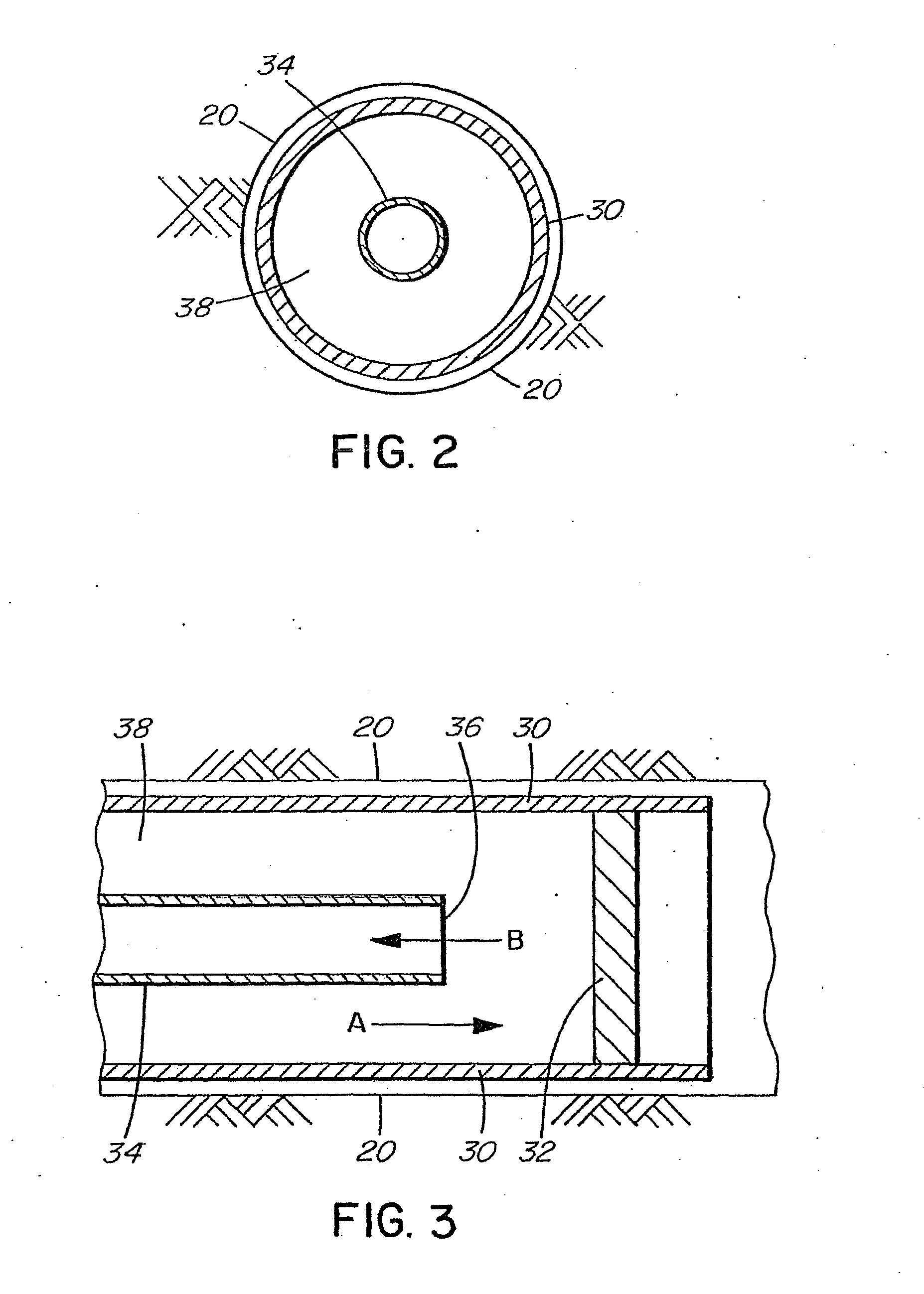
[0017]The basic module of the invention, a “circuit,” is an assembly of pipes inside a directionally drilled bore hole that extends from...


PUM


Abstract

A system and method to extract heat energy from underground heat sources, then transport that heat to the surface in the form of a high temperature liquid or gas, and deliver the contaminant-free heat energy to a surface user of heat. The heat captured in the working fluid of the system is gained by heat transfers and can be extracted from the in situ combustion of any oil sands, heavy oil, conventional or unconventional oil, bitumen, coal, conventional or unconventional natural gas, methane or oil shales, or from various other sources. The invention creates a closed circulation system, in which the working fluid and steam circulating in the system are protected from any direct contact with the hydrocarbon reservoir, and gases produced by the in situ combustion are sequestered in the reservoir by the overlying overburden.

Description

FIELD OF THE INVENTION[0001]The invention pertains to systems that extract heat energy from the in situ combustion of hydrocarbon reservoirs and from other sources of subterranean heat, and deliver that heat energy to the surface for use in generating electric power and other applications requiring heat.BACKGROUND OF THE INVENTION[0002]As part of the large-scale electrical power generation in the United States and Canada, massive burning of hydrocarbon fuels is required for power plants that are fired by coal, oil or natural gas. It is generally accepted that serious environmental problems arise during the production of electric power using any of these hydrocarbon fuels, albeit some less than others. Greenhouse gases are generated and released into the atmosphere, and many other contaminants are brought to the surface and must be dealt with using expensive and sometimes ineffective processes.[0003]With each step in the processes of extracting, refining, transporting and ultimately ...

Claims


Application Information

Patent Timeline
Patent Type & Authority Applications(United States)
IPC IPC(8): F24J3/08F02B63/04
CPCY02E10/125F24J3/083F24T10/15Y02E10/10
Inventor ROGERS, WILLIAM H.SMITH, MICHAEL J.
Owner 7238703 CANADA
Why Eureka
Try Eureka