System and method for cardiovascular exercise stress MRI

a stress-mri and cardiovascular exercise technology, applied in the field of cardiac stress testing, can solve the problems of patients not being able to reach peak effort, unsuitable for cardiac stress testing, unsatisfactory results, etc., and achieve the effect of short time laps

Inactive Publication Date: 2013-09-05
THE OHIO STATES UNIV
View PDF9 Cites 3 Cited by
  • Summary
  • Abstract
  • Description
  • Claims
  • Application Information

AI Technical Summary

Benefits of technology

[0012]The invention proceeds from the realization that an electric motor is the most massive ferromagnetic element in a conventional treadmill and that replacing that element with a non-ferromagnetic motor can greatly simplify the task of providing a treadmill that can be used inside the scan room. The invention further proceeds from the realization that if the treadmill motor that drives the belt is designed to produce rotational motion from pressurized fluid supplied to the motor, the motor can be made of non-ferromagnetic components and the fluid can be pressurized by a pump located outside the scan room.
[0014]Apparatus in accordance with the invention can be safely put inside the scan room because there is little (advantageously, no) ferromagnetic material to be attracted to the magnet or to distort the main field of the MR imager. Any appreciable quantity of ferromagnetic material is relocated out of the scan room where it cannot be attracted to the magnet of the MR imager and cannot adversely affect the quality of the MR image.
[0016]By using a method in accordance with the invention, the patient is very close to the MR imager and there is only a short time lapse between cessation of the patient's exercise and acquisition of the post-exercise MR image. It is therefore possible to acquire an MR image that is closely representative of an image of the patient's heart at peak effort.

Problems solved by technology

All have been unsatisfactory.
This was unsatisfactory because pharmacologically induced stress does not link physical activity to symptoms as treadmill exercise does.
While this was useful for certain research studies, it was unsuitable for cardiac stress testing.
Patients were unable to reach peak effort by cycling in a supine position because it was uncomfortable and because leg fatigue caused patients to cease exercising before they reached peak effort.
Although the results of this experiment were encouraging, the Rerkpattanapipat et al. experimental setup is not practical for clinical use.
Additionally, use of a treadmill outside the scan room raises safety concerns with moving a patient such a distance after (s)he has reached peak effort.
This was necessary because it would have been unwise and indeed unsafe to place a conventional treadmill in the scan room.
If a ferromagnetic object is in the scan room, the object will likely be pulled towards the imager with great force, potentially causing great damage to the imager and even causing serious injury to the patient.
For example, in one reported instance an oxygen tank located in the scan room was turned into a projectile when the imager was energized, causing injury to a pediatric patient.
Additionally, even if a ferromagnetic component were to be firmly fixed in position so that it could not come loose to cause equipment damage or patient injury, its presence in the scan room would be highly undesirable because it would distort the main magnetic field created by the imager.
This distortion would generate artifacts in the reconstructed MR image and possibly reduce the diagnostic utility of that image.

Method used


Image

  • System and method for cardiovascular exercise stress MRI
  • System and method for cardiovascular exercise stress MRI
  • System and method for cardiovascular exercise stress MRI

Examples


Embodiment Construction

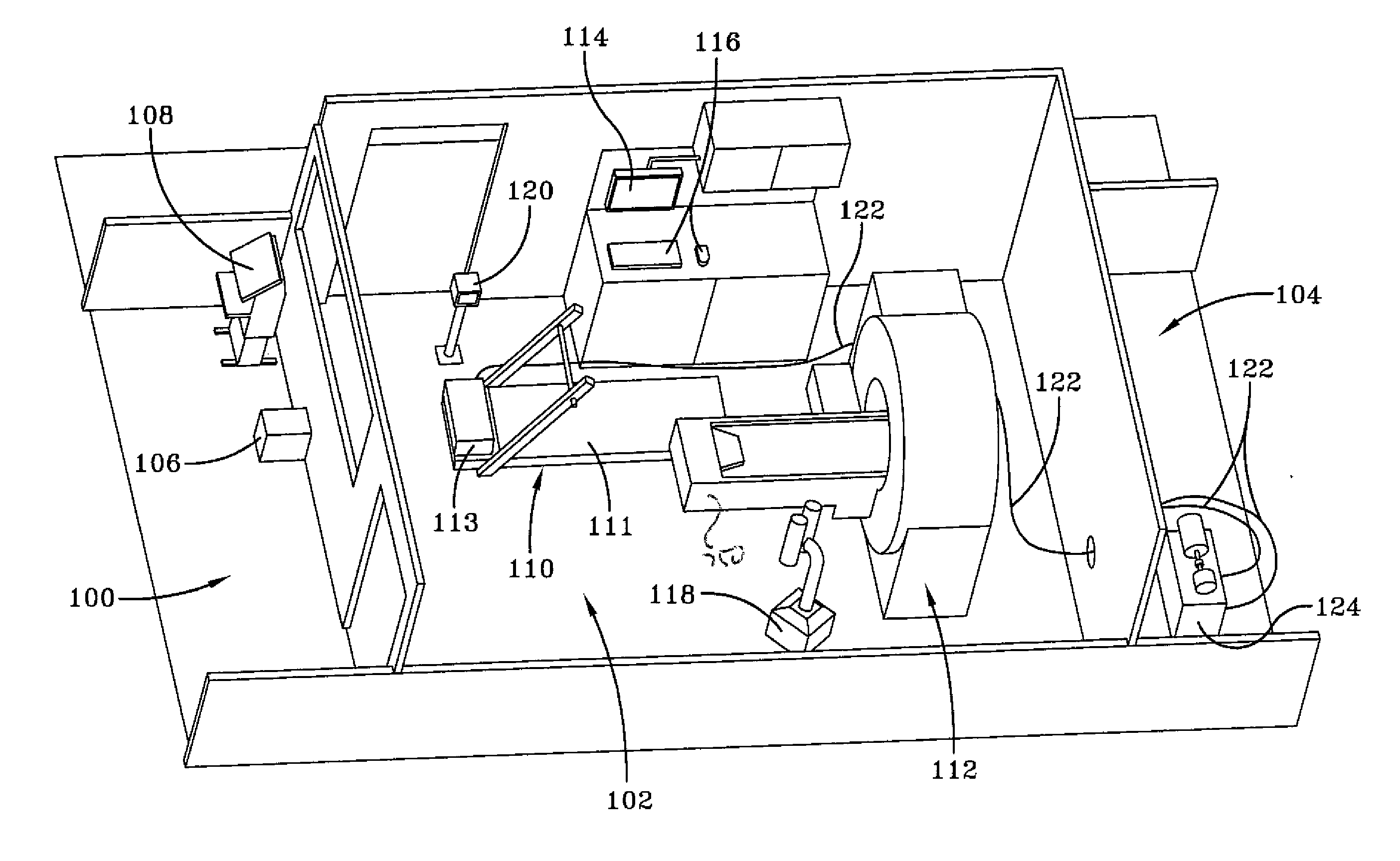
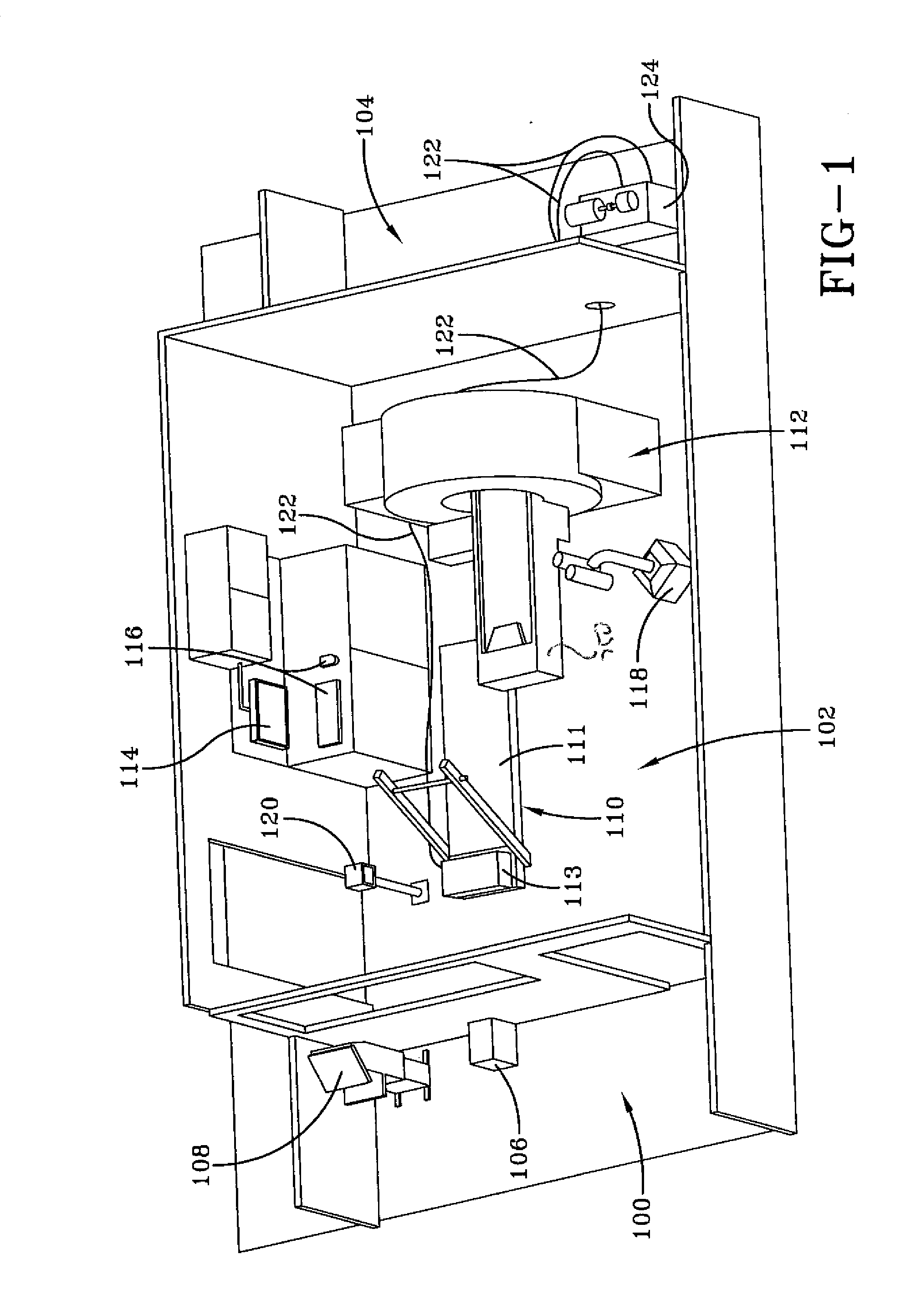
[0025]Referring to FIG. 1, an illustration of components and the configuration of components for a MR-compatible treadmill system according to an example embodiment of the present invention is shown. In this example, components of the present invention are contained in a control room 100, a scan room 102 and an equipment room 104. One or more computers 106 in the control room 100 support control and monitoring of components in the scan room 102. A treadmill control system computer may be used to communicate with the treadmill 110. Another scanner computer may be used to communicate with the MR imager 112. The scanner computer may be used to control functionaltiy of the MR imager 112 related to data acquisiton, image reconstruction, and image display and analysis.

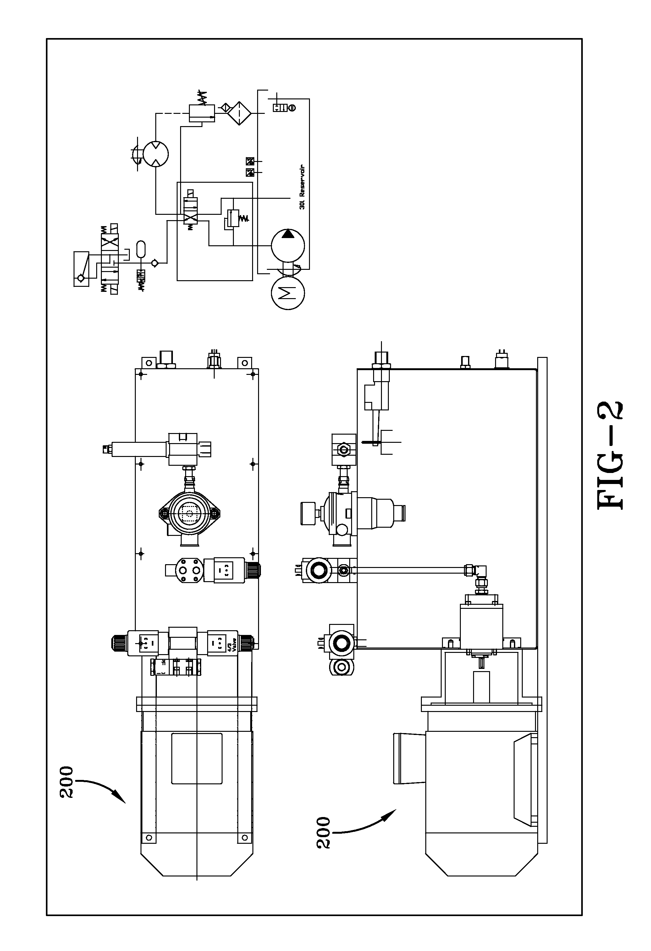
[0026]A hydraulic powered treadmill 110 and MR imager 112 are contained in the scan room 102. The hydraulic powered treadmill 110 is connected to a hydraulic power pack 124 via hydraulic hoses 122. In FIG. 1, certain hose se...


PUM


Abstract

A system and method for cardiovascular exercise stress magnetic resonance using a MR-compatible treadmill. The treadmill is made of non-ferromagnetic materials and has a belt driven by a motor that produces rotational motion from pressurized fluid that is produced by a pump located outside the scan room. The treadmill is adjacent to the MR imager. Patients complete an exercise protocol on the treadmill and are then transferred to the MR imager without leaving the scan room. Images are acquired as quickly as possible post-exercise to more accurately diagnose cardiovascular disease in patients.

Description

CROSS-REFERENCE TO RELATED APPLICATIONS[0001]This application is a continuation under 35 USC §120 of application Ser. No. 12 / 424,835 filed Apr. 16, 2009, which is a continuation of application number PCT / US07 / 81948, filed Oct. 19, 2007, titled SYSTEM AND METHOD FOR CARDIOVASCULAR EXERCISE STRESS MRI, which is in turn entitled to benefit of a right of priority under 35 USC §119 from U.S. Ser. No. 60 / 862,107, filed Oct. 19, 2006, titled MAGNETIC RESONANCE COMPATIBLE TREADMILL, both of which are herein incorporated by reference in their entirety.BACKGROUND OF THE INVENTION[0002]The invention relates to cardiac stress testing, and more particularly relates to cardiac stress testing using diagnostic medical imaging techniques. In its most immediate sense, the invention relates to cardiac exercise stress testing using magnetic resonance (“MR”) imaging.[0003]In an electrocardiogram (ECG) cardiac exercise stress test, a patient is connected to an ECG monitor and instructed to walk on a trea...

Claims


Application Information

Patent Timeline
Patent Type & Authority Applications(United States)
IPC IPC(8): A61B5/00A61B5/02
CPCA61B5/0046A61B5/055A61B5/222A61B5/02A63B21/158A63B22/02A61B5/0044A61B5/4884
Inventor SIMONETTI, ORLANDO PAULFOSTER, ERIC LEEARNOLD, JOHN WAYNERAMAN, SUBHA V.
Owner THE OHIO STATES UNIV
Why Eureka
Try Eureka