
Antenna system

a technology of antennas and antennas, applied in the field of radio communications, can solve the problems of increased hardware costs, transmission loss, limited flexibility, etc., and achieve the effect of reducing labor and equipment costs and reducing feeder losses

Active Publication Date: 2013-09-05
HUAWEI TECH CO LTD
View PDF3 Cites 25 Cited by
  • Summary
  • Abstract
  • Description
  • Claims
  • Application Information

AI Technical Summary

Benefits of technology

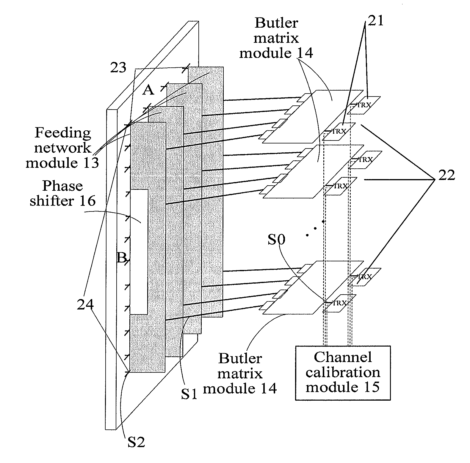
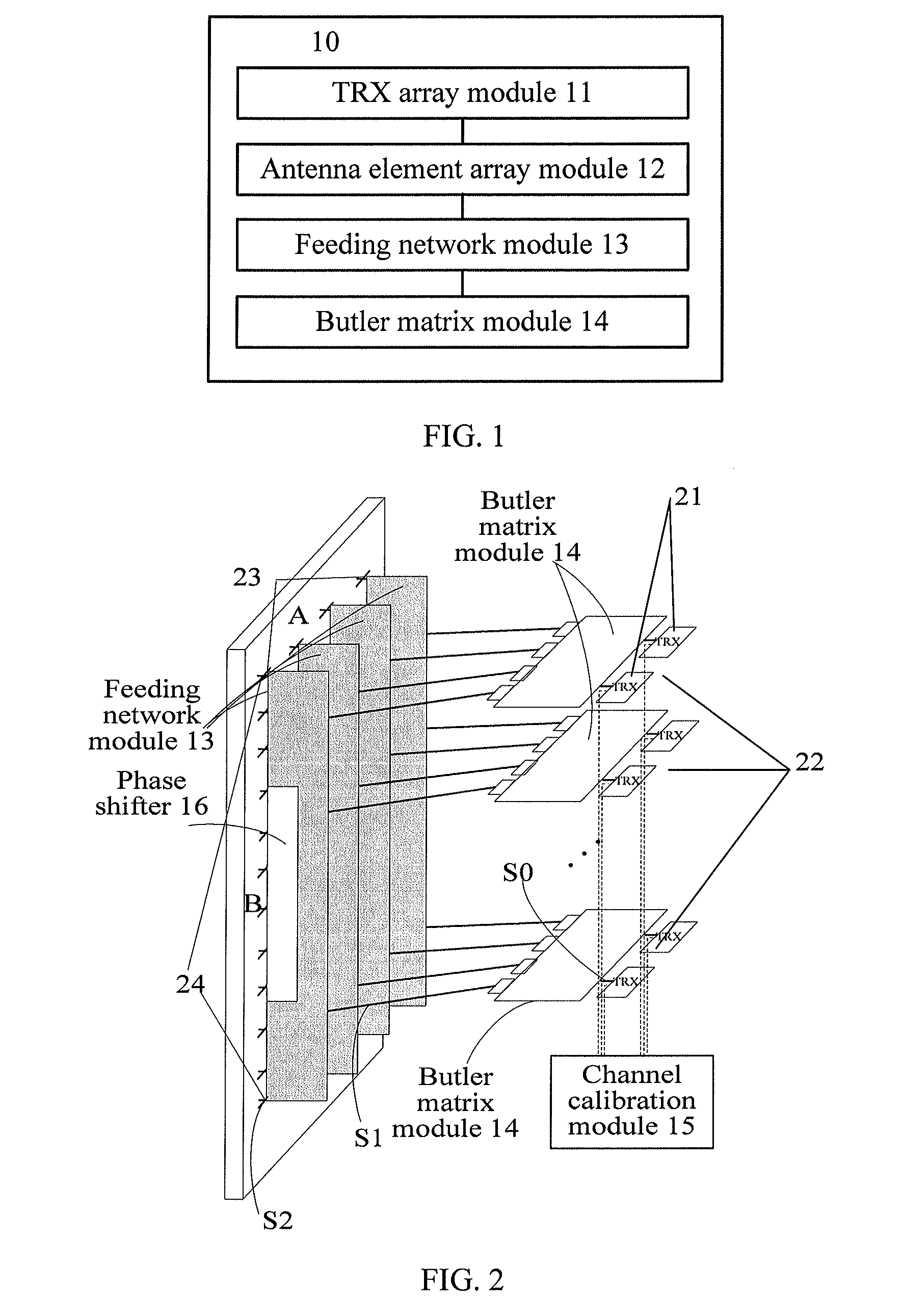
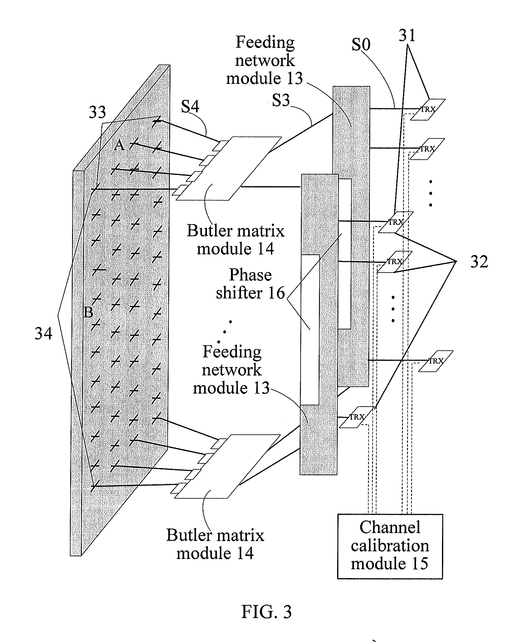
The present invention introduces an antenna system that is designed to minimize expenses. This system is built on the basis of an AAS antenna and has various benefits such as reducing feeder loss, decreasing labor and equipment costs, offering better vertical and horizontal beam characters, and also enhancing spectrum resource utilization rate.

Problems solved by technology

1. Install the antenna in a tilt status. The formed direction of the main lobe, also known as the tilt angle, has already been fixed in design, which is referred to as fixed electrical tilt (FET, Fixed Electrical Tilt). The tilt angle cannot be changed unless an operator climbs up the tower of the base station to adjust or change an installation support.
2. Dispose a phase shifter inside the antenna, so that the antenna becomes a manual electrical tilt (MET, Manual Electrical Tilt) antenna. When the tilt angle needs to be changed, an operator needs to climb up the tower to adjust the phase shifter, which is also quite inconvenient.
3. Add a motor device on the basis of the antenna in the manner 2, being used for remote control. The antenna of the base station is referred to as a remote electrical tilt (RET, Remote Electrical Tilt) antenna. The hardware increases costs. Besides, the electrical tilt in such manner cannot be separately configured according to different carrier waves and different channels, so the flexibility is limited.
In the connection, transmission loss exists.
Besides, a discrete component increases the equipment costs, and also increases the labor costs of maintenance.

Method used


Image

  • Antenna system
  • Antenna system
  • Antenna system

Examples


Embodiment Construction

[0024]The following clearly and completely describes the technical solutions according to the embodiments of the present invention with reference to the accompanying drawings in the embodiments of the present invention. Apparently, the embodiments in the following description are merely a part rather than all of the embodiments of the present invention. All other embodiments obtained by persons of ordinary skill in the art based on the embodiments of the present invention without creative efforts shall fall within the protection scope of the present invention.

[0025]The technical solutions provided by the embodiments of the present invention may be applied in various communication systems, such as a global system for mobile communication (GSM, Global System for Mobile Communication) system, a code division multiple access (CDMA, Code Division Multiple Access) system, a wideband code division multiple access wireless (WCDMA, Wideband Code Division Multiple Access Wireless) system, a g...


PUM


Abstract

An antenna system, including: a TRX array module, an antenna element array module, a feeding network module and a Butler matrix module, is provided. The TRX array module includes multiple active TRX submodules and is configured to generate transmission signals that have undergone digital beam forming. The antenna element array module includes multiple antenna elements and is configured to transmit the transmission signals. The feeding network module is configured to form a vertical beam characteristic of the antenna element array module before the antenna element array module transmits the transmission signals. The Butler matrix module is configured to form a horizontal beam characteristic of the antenna element array module before the antenna element array module transmits the transmission signals. The antenna system reduces the feeder loss, reduces the labor and equipment costs, and enables the vertical and horizontal beam characteristics of the antenna to be adjusted more conveniently.

Description

CROSS-REFERENCE TO RELATED APPLICATIONS[0001]This application is a continuation of International Application No. PCT / CN2012 / 071941, filed on Mar. 5, 2012, which is hereby incorporated by reference in its entirety.FIELD OF THE INVENTION[0002]The present invention relates to the field of radio communications, and in particular, to an antenna system of a base station.BACKGROUND OF THE INVENTION[0003]An antenna of a base station is used to transform radio frequency signals into electromagnetic wave signals, and radiate the electromagnetic wave signals to the space; or receive electromagnetic wave signals transmitted from a terminal, transform the electromagnetic wave signals into radio frequency signals and deliver the radio frequency signals to the base station.[0004]Each antenna controls a certain range of area, and the area is referred to as a sector or a cell. Electromagnetic waves are radiated or received in the area, and a radiation radius is controlled by using a method for contr...

Claims


Application Information

Patent Timeline
IPC IPC(8): H01Q3/40
CPCH01Q3/40H01Q1/246H01Q21/0025
Inventor PU, TAOHE, PINGHUAMAO, MENGDA
Owner HUAWEI TECH CO LTD
Learn More