Drug support body, and method for producing same
a technology of support body and drug, which is applied in the direction of identification means, paper/cardboard containers, instruments, etc., can solve the problems of not being able to maintain the drug in sterile condition, and achieve the effect of convenient handling of the drug support body
- Summary
- Abstract
- Description
- Claims
- Application Information
AI Technical Summary
Benefits of technology
Problems solved by technology
Method used
Image

Examples
first embodiment
[0075]A first embodiment of the drug support body 1 of the present invention will be described with reference to the drawings.
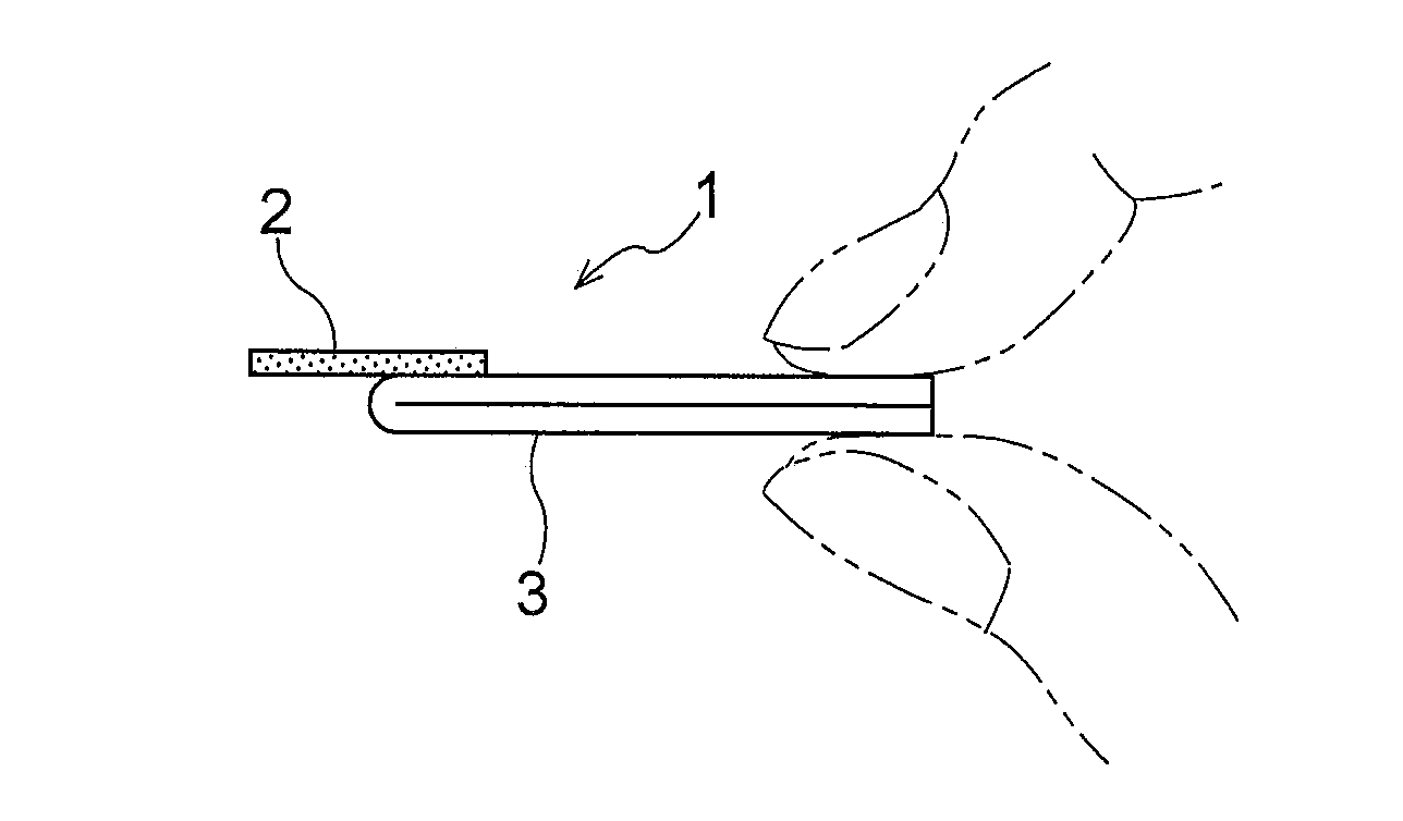
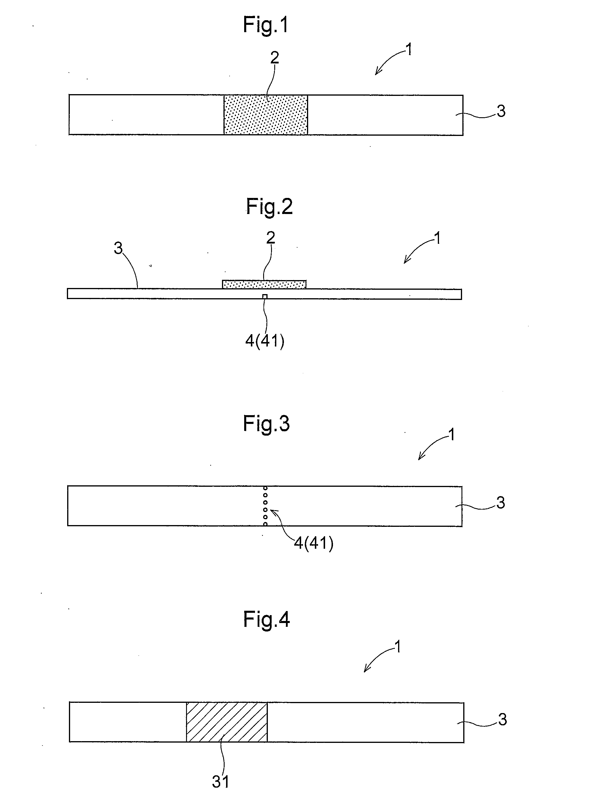
[0076]As shown in FIGS. 1 to 3, the drug support body 1 includes a base plate 3, and a drug layer 2 provided on one surface of the base plate 3.
[0077]The base plate 3 has, for example, an elongated rectangular shape. The base plate 3 may be formed of any appropriate material, such as, but not particularly limited to, paper, plastic, aluminum foil or the like. The base plate 3 may also be formed of a stack of a plurality of layers of these materials.
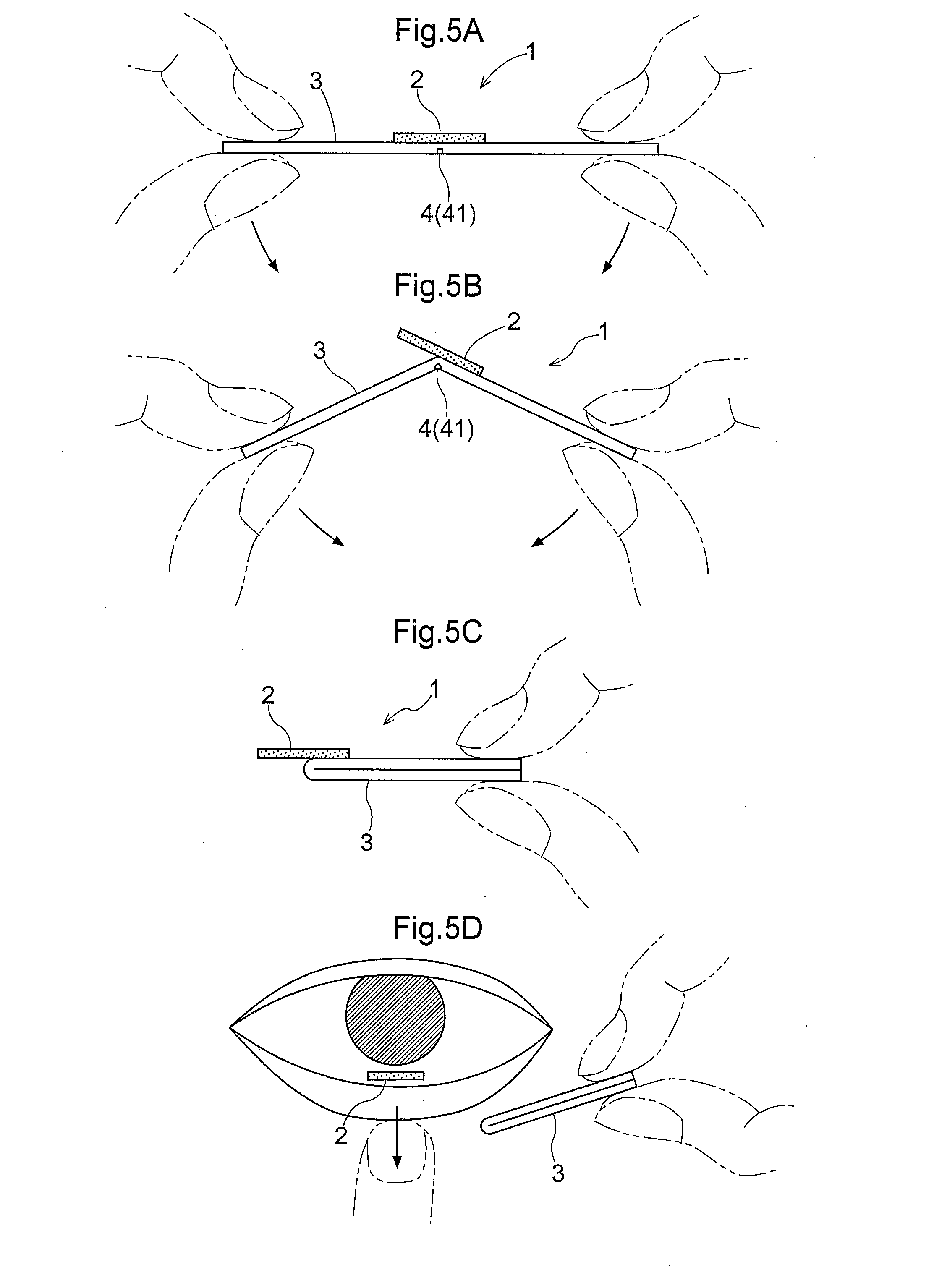
[0078]As shown in FIGS. 2 and 3, a bending portion 4 at which the base plate 3 can be bent is provided at a middle portion in a longitudinal direction of the base plate 3. In this embodiment, a perforation 41 is formed in the bending portion. The perforation 41 is provided in one surface of the base plate 3 that is opposite to another surface on which the drug layer 2 is provided, extending along a direction perpen...
second embodiment
[0090]A second embodiment of the drug support body 1 of the present invention will be described with reference to the drawings.
[0091]In this embodiment, the sticking force of the drug layer 2 (solid composition) to the base plate 3 varies between a predetermined region including the bending portion 4 and the other region. Specifically, for example, as shown in FIG. 8, in the longitudinal direction of the base plate 3, the surface of the base plate 3 on which the drug layer 2 is formed is formed of different materials in different regions (i.e., the bending portion 4 and predetermined regions on both sides of the bending portion 4 (at-and-near-bending-portion region), and regions closer to the end portions than is the at-and-near-bending-portion region) so that the regions closer to the end portions than is the at-and-near-bending-portion region have a higher releasability and therefore a smaller sticking force between the base plate 3 and the drug layer 2. Specifically, the release ...
third embodiment
[0093]A third embodiment of the drug support body 1 of the present invention will be described with reference to the drawings.
[0094]In an example shown in FIG. 10A-10C, bending portions 4a and 4b are formed at two points of the base plate. The bending portion 4a is located at a substantially middle portion in the longitudinal direction of the drug layer 2. The bending portion 4b above which the drug layer 2 is not formed is located at a point that is closer to one end portion of the base plate 3 than is the middle portion in the longitudinal direction of the base plate 3. The bending portion 4a above which the drug layer 2 is formed is formed in a region whose distance between the bending portion 4b and the end portion of the base plate 3 is longer. In this embodiment, as in the second embodiment, the surface of the base plate on which the drug layer 2 is formed is formed of different materials in different regions (i.e., the bending portion 4a and predetermined regions on both side...
PUM
 Abstract
Description
Claims
Application Information
 - R&D
- Intellectual Property
- Life Sciences
- Materials
- Tech Scout
- Unparalleled Data Quality
- Higher Quality Content
- 60% Fewer Hallucinations
Browse by: Latest US Patents, China's latest patents, Technical Efficacy Thesaurus, Application Domain, Technology Topic, Popular Technical Reports.
© 2025 PatSnap. All rights reserved.Legal|Privacy policy|Modern Slavery Act Transparency Statement|Sitemap|About US| Contact US: help@patsnap.com