
Method and system for painting a part of a motor vehicle body

a motor vehicle and body technology, applied in the direction of nuclear engineering, transportation and packaging, railway signalling, etc., can solve the problems of not being able to meet the needs of a large number of customers, not being able to deposit parts in waiting areas, etc., and achieve the effect of improving the quality and reducing the cos

Inactive Publication Date: 2013-08-29
CO PLASTIC OMNIUM
View PDF8 Cites 5 Cited by
  • Summary
  • Abstract
  • Description
  • Claims
  • Application Information

AI Technical Summary

Benefits of technology

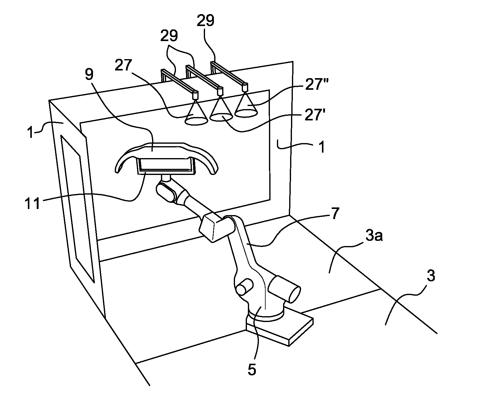
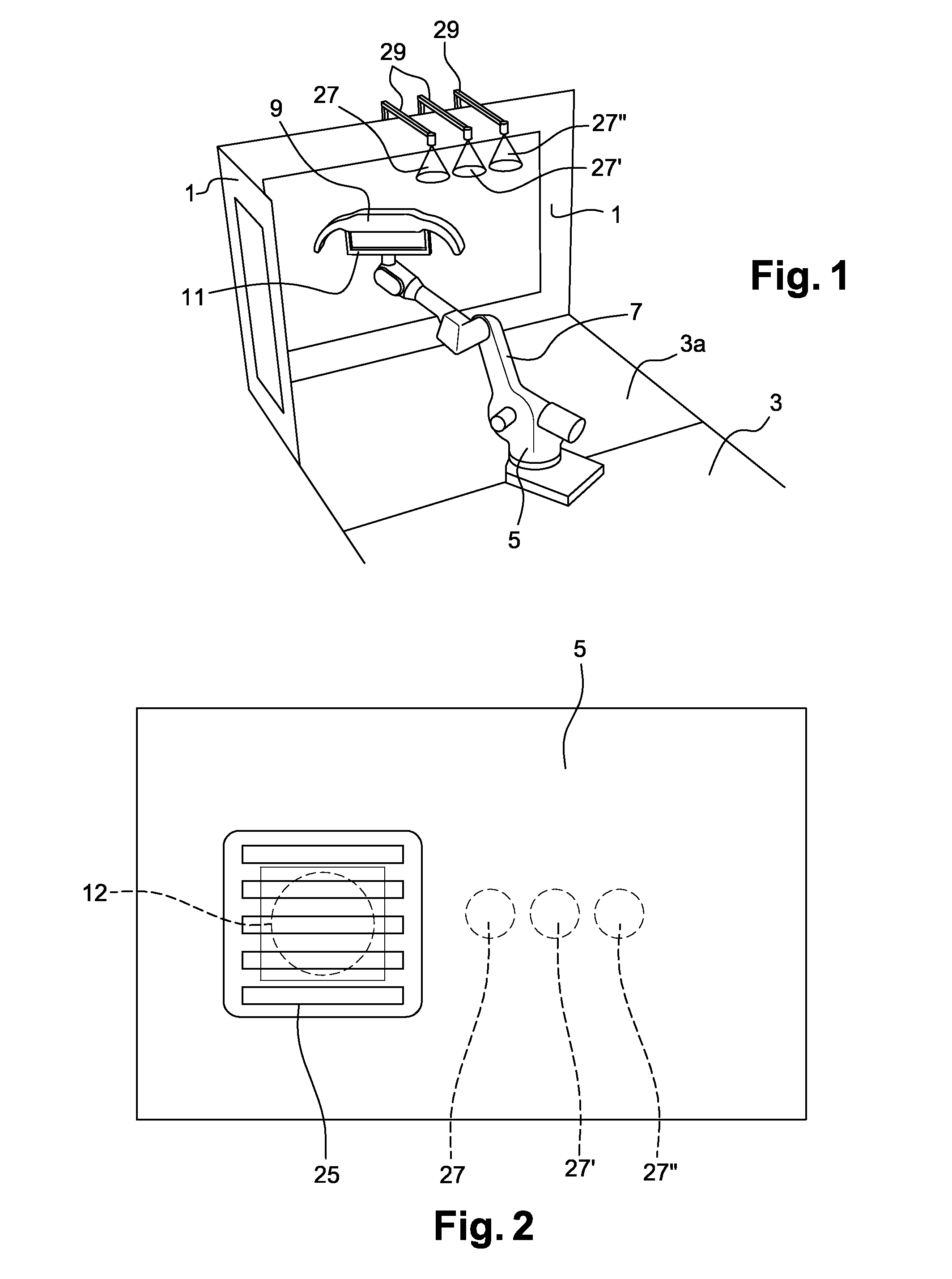
The invention relates to booth type painting installations where parts are moved by a handler robot, instead of being transferred through a series of workstations. This change in design allows for better and less expensive conditions for applying paint. The invention also includes a method for controlling air streams to spray paint particles. By depositing parts in a waiting zone or nearby booth and using the robot to process another part during flash-off time, the robot's usage is maximized, resulting in a better return on the expensive investment. In one implementation, the robot moves the part to expose the entire surface to flash-off acceleration means, reducing the duration of flash-off. This allows for the use of highly localized, compact, inexpensive, and energy-consuming flash-off acceleration means. The invention also addresses the issue of lengthening the path between workstations for applying paint components in a painting line. The robot enables avoidance of this issue when the line is transformed for applying aqueous components.

Problems solved by technology

Nevertheless, the inventors have carried out tests on the handling of parts by the robot during flash-off time, and they have found that, contrary to received ideas, it is not necessarily most efficient to deposit a part in a waiting zone.
The robot thus contributes to reducing the duration of flash-off by optimizing the exposure of the part in front of the acceleration means, which means may then present a limited field of application.

Method used


Image

  • Method and system for painting a part of a motor vehicle body
  • Method and system for painting a part of a motor vehicle body

Examples


Embodiment Construction

[0044]In order to begin by explaining the advantage of the invention, it is appropriate to recall that it differs from a more conventional solution consisting in placing a freshly-painted part in a waiting zone to allow it a flash-off time between two applications of paint components.

[0045]However, leaving a part to perform its flash-off in a waiting zone implies firstly a significant increase in the tasks to be performed by the robot (e.g. placing a first part in the waiting zone, placing a second part in the waiting zone, taking back the first part, taking back the second part, etc.), and implies secondly investments and surface areas in installations that are reserved for this waiting zone (e.g.: a second booth fitted with stacking means, a ventilation system and a communicating airlock controlled together with the painting booth).

[0046]These observations are summarized in the comparative table below which lists the operations and the movements performed by the robot under two co...


PUM


Abstract

The invention relates in particular to a method of painting a motor vehicle bodywork part, the method comprising the steps consisting in applying a first component on the part, in allowing the first component to tension on said part during a so-called “flash-off” stage, then in applying a second component on the part, the part being moved by a handler robot in front of a stationary applicator during the two spraying steps and in front of flash-off acceleration means during the flash-off stage. The invention also provides a painting booth having at least one stationary applicator for applying a paint component on a part carried by an arm of a handler robot that is present in the booth, and means for accelerating the flash-off of the part, the means being arranged in the booth in such a manner that the part can enter into the field of action of the acceleration means while being carried by the same handler robot.

Description

FIELD OF THE INVENTION[0001]The invention relates to the field of painting motor vehicle bodywork parts.BACKGROUND OF THE INVENTION[0002]Motor vehicle parts are often painted in a painting production line that is in the form of an installation in which hangers carrying a plurality of parts for painting travel one after another through a succession of workstations. A painting line may also comprise workstations for performing the following actions in succession:[0003]flaming;[0004]applying a primer;[0005]possibly stoving for drying if the primer uses water as its solvent (the primer is then said to be water-based, otherwise it is solvent-based);[0006]applying a base;[0007]possibly stoving once more for drying if the base is a water-based base;[0008]applying varnish; and[0009]heating for baking.[0010]The substances referred to as “primer”, “base”, and “varnish”, are also referred to as “paint components”.[0011]Transferring parts between two workstations takes the length of time needed...

Claims


Application Information

Patent Timeline
Patent Type & Authority Applications(United States)
IPC IPC(8): B05B15/12B05B16/00
CPCB05B13/0285B05D1/02B05D3/0263B05D3/067B05B15/1288B05D7/544B05D3/0413B05B13/0221B05B16/90
Inventor VIDAL, SOPHIE
Owner CO PLASTIC OMNIUM
Learn More