
Economical timepiece barrel

a timepiece and economic technology, applied in the field of timepiece barrels, can solve the problems of insufficient automatic assembly of the whole unit, inability to secure the ratchet, and generally using screws, and achieve the effect of easy automatic extraction and convenient us

Active Publication Date: 2013-08-29
ETA SA MFG HORLOGERE SUISSE
View PDF6 Cites 11 Cited by
  • Summary
  • Abstract
  • Description
  • Claims
  • Application Information

AI Technical Summary

Benefits of technology

The invention is a barrel that can be easily automated to assemble and mount in a higher order assembly, such as a movement. It is designed to be easily extracted from the assembly. The invention reduces production and assembly costs, simplifies the barrel assembly process, and allows components to be joined in sub-assembly stages, reducing the need for labor-intensive assembly operations. The barrel remains removable once the movement is assembled. Additionally, the invention improves shock resistance by locking the barrel arbour, which passes through the walls of the structure and is rigidly stopped by the first and second arbour stopping surfaces.

Problems solved by technology

Few configurations permit both automated assembly and easy removal of the barrel from the movement during a maintenance operation.
In the first case where the cover is fixed to the drum and independent of the ratchet, it is impractical to secure the ratchet, generally using screws, in an automated manner.
In the second case, where the ratchet alone closes the barrel, it is only the barrel spring itself that securely holds the barrel, which is insufficient to permit automated assembly of the whole unit.
In both the first and second case, under the effect of accelerations and particular in the event of a shock, the barrel is liable to move away from its pivoting points, and no longer be able to perform the function of driving the movement to which it is dedicated.

Method used


Image

  • Economical timepiece barrel
  • Economical timepiece barrel
  • Economical timepiece barrel

Examples


Embodiment Construction

[0053]The invention concerns the field of horology, and more specifically the field of energy storage using a barrel with a barrel spring for a drive movement or striking work movement.

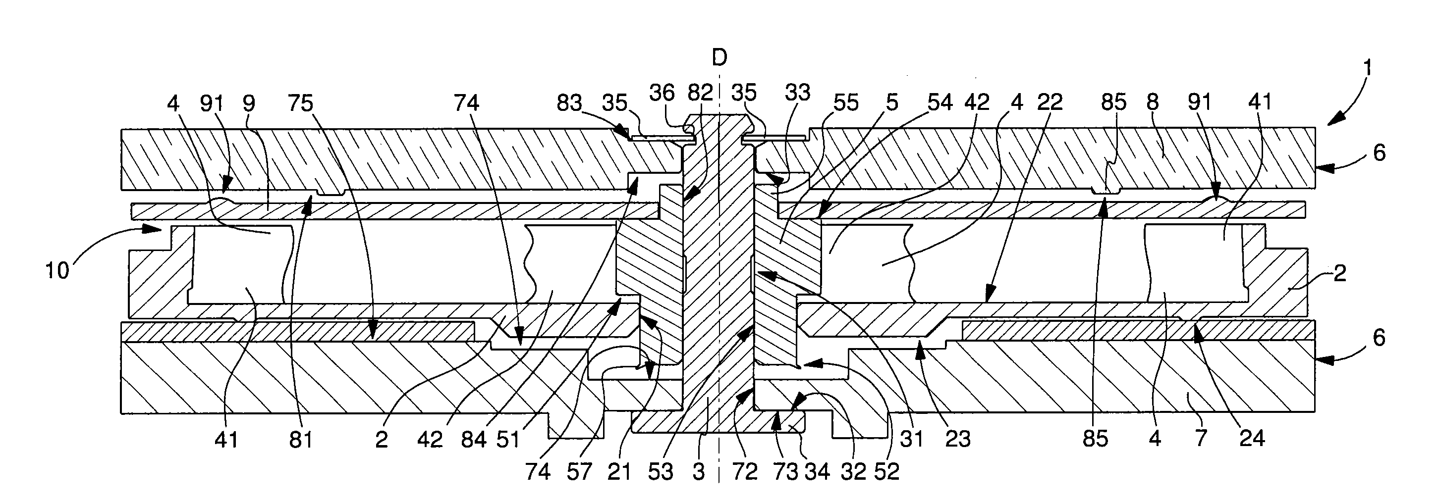
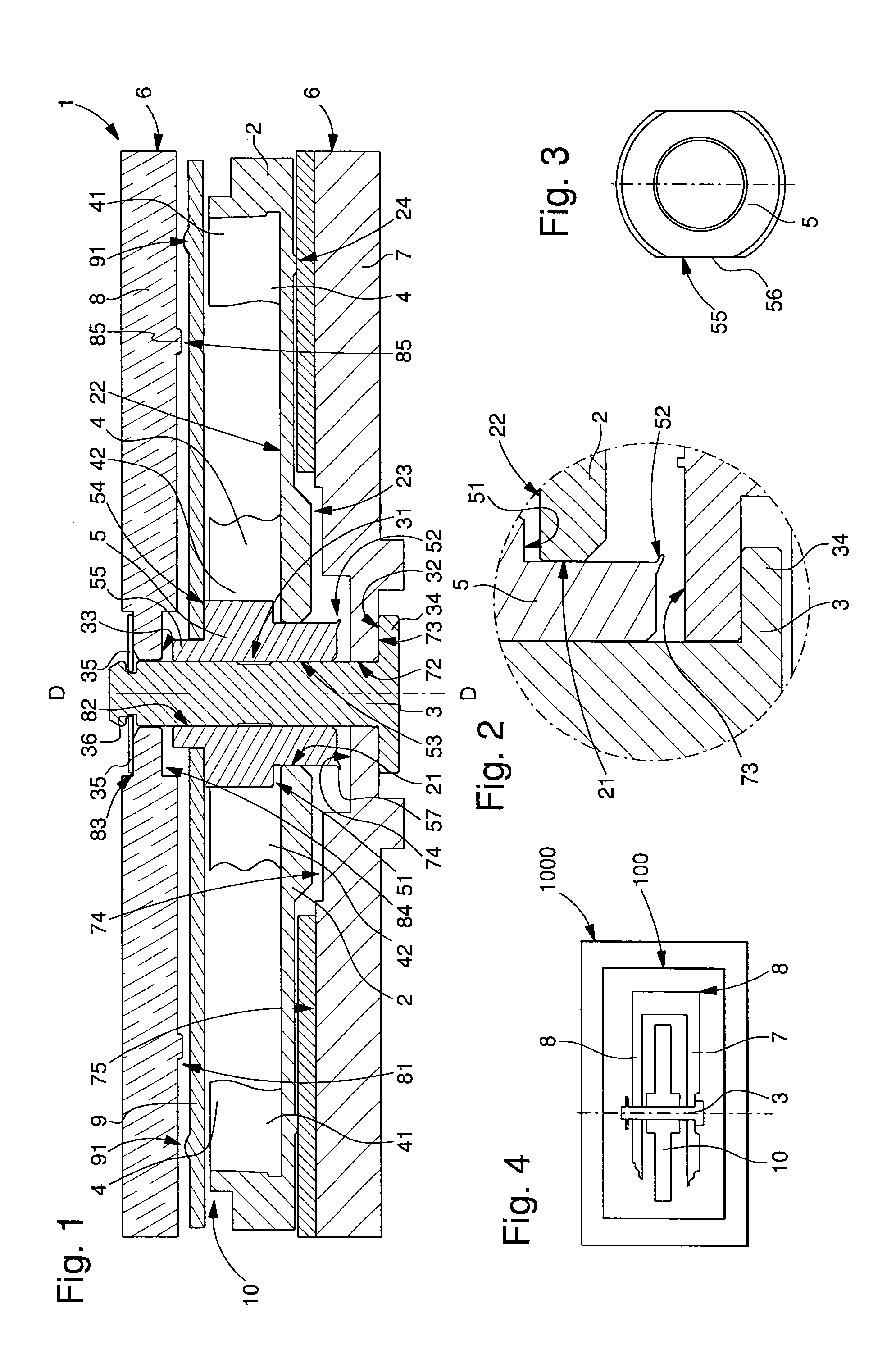
[0054]The invention concerns a timepiece barrel 1, mounted between a bottom plate 7 and a bar 6 and including a drum 2 coaxial to a barrel arbour 3 in a direction of pivoting D.

[0055]This drum 2 is arranged to confine at least one barrel spring 4 a first end 41 of which is fixed or hooked to said drum 2, or cooperates with the drum 2 where spring 4 is adherently mounted with a sliding bridle, and a second end 42 of which is fixed or hooked to a core 5, which is coaxial to said barrel arbour 3 and guided on barrel arbour 3, on a hook 43 or similar.

[0056]Core 5 is pivotally guided in a bore 21 comprised in drum 2 and includes a first core limiting surface 51, arranged to limit the axial travel, in pivoting direction D, of core 5 relative to an inner surface 22 of drum 2, and a second core stopping surfa...


PUM

PropertyMeasurementUnit
Timeaaaaaaaaaa

Abstract

Timepiece barrel (1) with a drum (2) coaxial to a barrel arbour (3) in a direction (D) arranged to confine a barrel spring (4) hooked to said drum (2) and to a core (5) coaxial to said barrel arbour (3) and guided thereon.Said core (5) pivots in a bore (21) of said drum (2), and includes a first stopping surface (51) limiting the axial travel of said core (5), in said direction (D), relative to an inner face (22) of said drum (2), and a second stopping surface (52) opposite the first (51) and limiting the axial travel of said core (5), relative to an outer face (23) of said drum (2), which is arranged, on the one hand, imprisoned between said first stopping surface (51) and said second stopping surface (52), and on the other hand to pivot freely about said core (5).

Description

[0001]This application claims priority from European Patent Application No. 12157575.7 filed Feb. 29, 2012, the entire disclosure of which is incorporated herein by reference.FIELD OF THE INVENTION[0002]The invention concerns a timepiece barrel including a pivoting drum comprising a toothing, coaxial to a barrel arbour in a direction of pivoting, said drum being arranged to confine at least one barrel spring, a first end of which is fixed or hooked to said drum, and a second end of which is fixed or hooked to a core, which is coaxial to said barrel arbour and guided on said barrel arbour.[0003]The invention concerns a timepiece movement incorporating at least one barrel of this type.[0004]The invention concerns a timepiece including a timepiece movement of this type and / or at least one barrel of this type.[0005]The invention concerns the field of horology, and more specifically the field of energy storage using a barrel with a barrel spring for a drive movement or striking work move...

Claims


Application Information

Patent Timeline
IPC IPC(8): G04B1/16
CPCG04B1/16Y10T29/49826G04B33/14
Inventor CATTIN, CHRISTOPHELOEFFEL, RAPHAELFEUSIER, GAEL
Owner ETA SA MFG HORLOGERE SUISSE
Learn More