Liquid consumption device and method

a technology of liquid consumption and reflected light, which is applied in the direction of printing, etc., can solve the problems of decreasing the light volume of reflected light, and achieve the effects of good precision, good precision and good precision

Active Publication Date: 2013-08-29
SEIKO EPSON CORP
View PDF4 Cites 1 Cited by
  • Summary
  • Abstract
  • Description
  • Claims
  • Application Information

AI Technical Summary

Benefits of technology

The present invention provides a liquid consumption device technology that can accurately determine the residual state of liquid inside a container mounted in the device. This is achieved by measuring the light volume of light reflected from a prism on the outer surface of the container. Additionally, the emitted light volume of the device is adjusted based on the reflected light from the prism in the container, so any dirtiness or accumulation of dirt is resolved. A threshold value is determined based on the reflected light volume to enable accurate detection of the liquid residual state. Furthermore, a plurality of liquid containers can be detected simultaneously without the need for individual adjustments of the emitted light volume. Overall, this technology provides a faster and more accurate way to determine the remaining liquid level in a liquid consumption device.

Problems solved by technology

However, with an inkjet type printing device, there is the risk that the ink mist generated with spraying of ink will adhere to the calibration reflection plate, decreasing the light volume of reflected light.
This kind of problem is not limited to inkjet method printing devices, but is a problem common to devices that detect the liquid residual state using a prism.

Method used


Image

  • Liquid consumption device and method
  • Liquid consumption device and method
  • Liquid consumption device and method

Examples


modification examples

E. Modification Examples

[0109]Above, we described embodiments of the present invention, but the present invention is not limited to this kind of embodiment, and it is possible to use various constitutions in a range that does not stray from its gist. For example, the following kinds of modifications are possible.

modification example 1

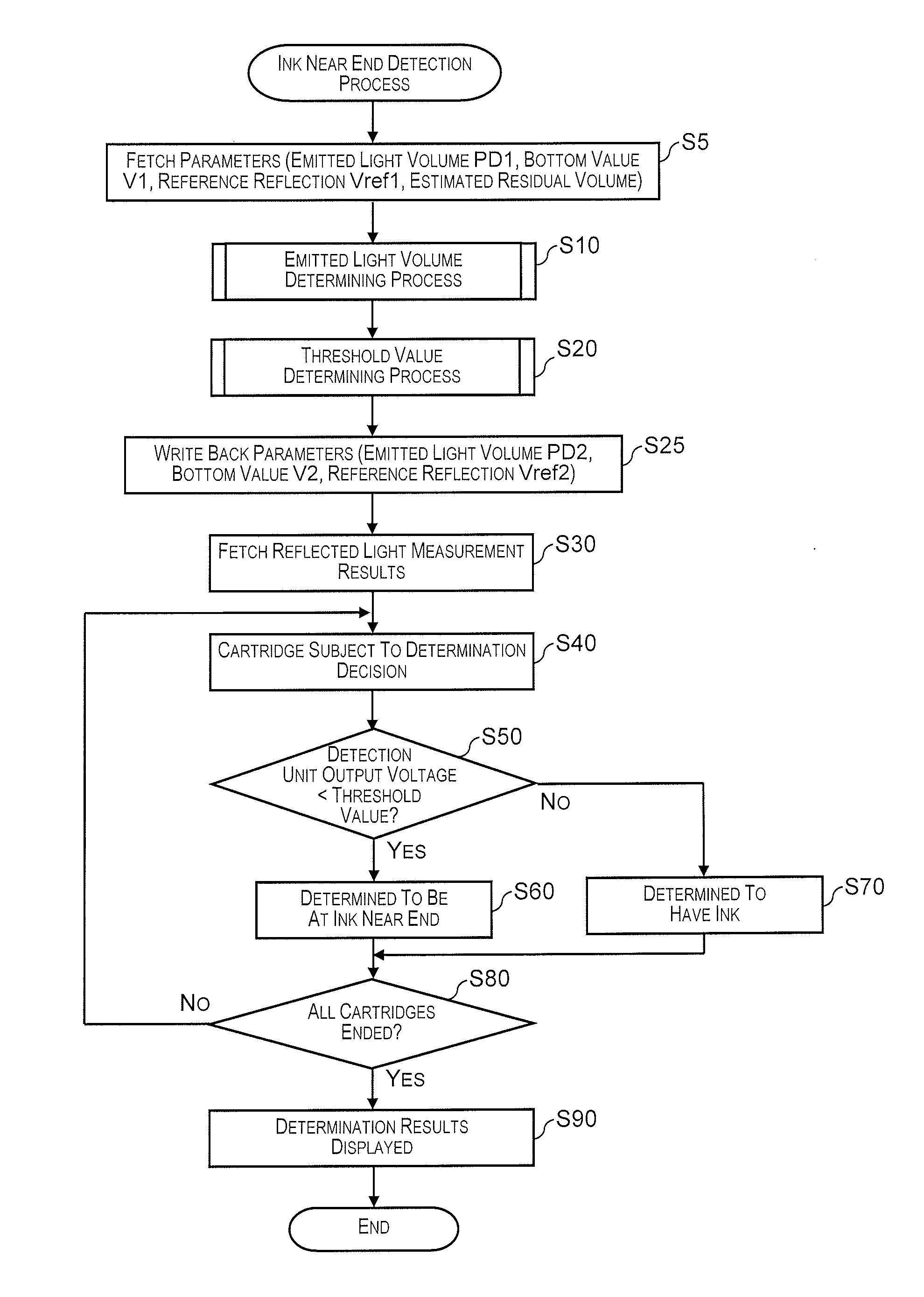
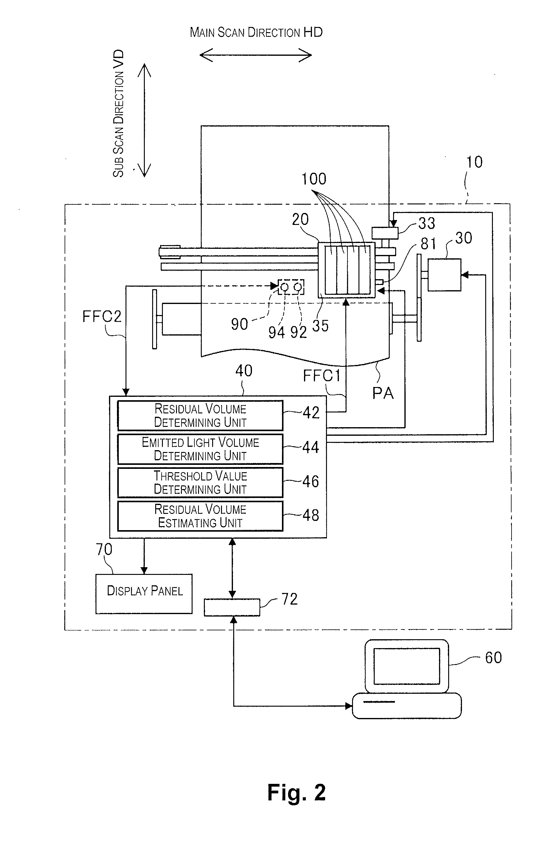
[0110]With the threshold value determining process shown in FIG. 12, the threshold value is calculated based on the bottom value corresponding to the emitted light volume determined by the emitted light volume determining process. In contrast to this, for example, it is also possible to have the emitted light volume of the light emitting unit 90 be set so that the output voltage of the detection unit 90 according to the reflected light from the reflection plate 81 is a predetermined voltage, and to measure the bottom value corresponding to that emitted light volume and calculate the threshold value. In other words, it is also possible to have the bottom value determined by the emitted light volume determining process and the bottom value that is the threshold value calculation reference for the threshold value determining process be different bottom values.

modification example 2

[0111]With the embodiments noted above, the light blocking mask 50 is provided at the center part of the bottom surface of the prism 170, but the light blocking mask 50 can also be omitted. In this case, the bottom value shown in FIG. 7 can be at one location rather than at two locations for each ink cartridge 100.


PUM


Abstract

A liquid consumption device includes a liquid container, a prism, a light emitting unit, a light receiving unit and a control unit. The prism is provided to the liquid container, and configured to receive light that is made incident from outside and to emit the incident light toward the outside according to a liquid residual state inside the liquid container. The control unit is configured to determine a threshold value of the liquid container for determining a light radiation volume by the light emitting part and / or the liquid residual state, based on a light volume of reflected light reflected by an outer surface of the prism and received by the light receiving unit upon radiation of the light by the light emitting unit. The control unit is configured to determine the liquid residual state based on a light volume of the light received by the light receiving unit.

Description

CROSS-REFERENCE TO RELATED APPLICATIONS[0001]This application claims priority to Japanese Patent Application No. 2012-037268 filed on Feb. 23, 2012 and Japanese Patent Application No. 2012-037272 filed on Feb. 23, 2012. The entire disclosures of Japanese Patent Application Nos. 2012-037268 and 2012-037272 are hereby incorporated herein by reference.BACKGROUND[0002]1. Technical Field[0003]The present invention relates to a liquid consumption device and method.[0004]2. Related Art[0005]Typically, an ink cartridge which is a detachable liquid container is mounted on an inkjet method printing device which is an example of a liquid consumption device. To optically detect the residual state of the ink inside, there are ink cartridges for which a prism is equipped.[0006]Regarding technology for detecting the ink residual state using a prism, for example, the printing device noted in Japanese Laid-Open Patent Application Publication No. H08-114488 uses a calibration reflecting unit provided...

Claims


Application Information

Patent Timeline
IPC IPC(8): B41J2/175
CPCB41J2/17566B41J2002/17573
Inventor NISHIHARA, YUICHI
Owner SEIKO EPSON CORP
Why Eureka
Try Eureka