
Cochlear implant fitting system

a cochlear implant and fitting system technology, applied in the field of electrical stimulation and frequency mapping of an installed cochlear implant, can solve the problems of ci's deformation, frequency shift, and difficulty in detecting the ci signal, and achieve the effect of reducing the difficulty of speech processing

Active Publication Date: 2013-08-22
NEW YORK UNIV
View PDF2 Cites 10 Cited by
  • Summary
  • Abstract
  • Description
  • Claims
  • Application Information

AI Technical Summary

Benefits of technology

The present invention is about a system and method for giving real-time electrical stimulation to a patient with a cochlear implant. The system allows a user to adjust the stimulation parameters in real-time, while the patient is hearing the sounds. The system also creates a frequency map that can be adjusted by the user with a short break between stimulation. The invention can also be used in combination with a hearing aid or to provide different levels of stimulation to the patient's two ears. Overall, the invention provides a flexible and efficient way to optimize the performance of cochlear implants for patients.

Problems solved by technology

Even after programming has been completed, the distortion of auditory input associated with CI's (e.g., spectral degradation and frequency shift) often requires extensive perceptual learning on the part of the patient.
Spectral degradation in the CI is caused by the limited number of stimulation channels while frequency shift results from physical limitations on the electrode insertion depth which may cause a mismatch between the speech processor's analysis filters and the characteristic frequency of the neurons stimulated by the electrodes.

Method used


Image

  • Cochlear implant fitting system
  • Cochlear implant fitting system
  • Cochlear implant fitting system

Examples


Embodiment Construction

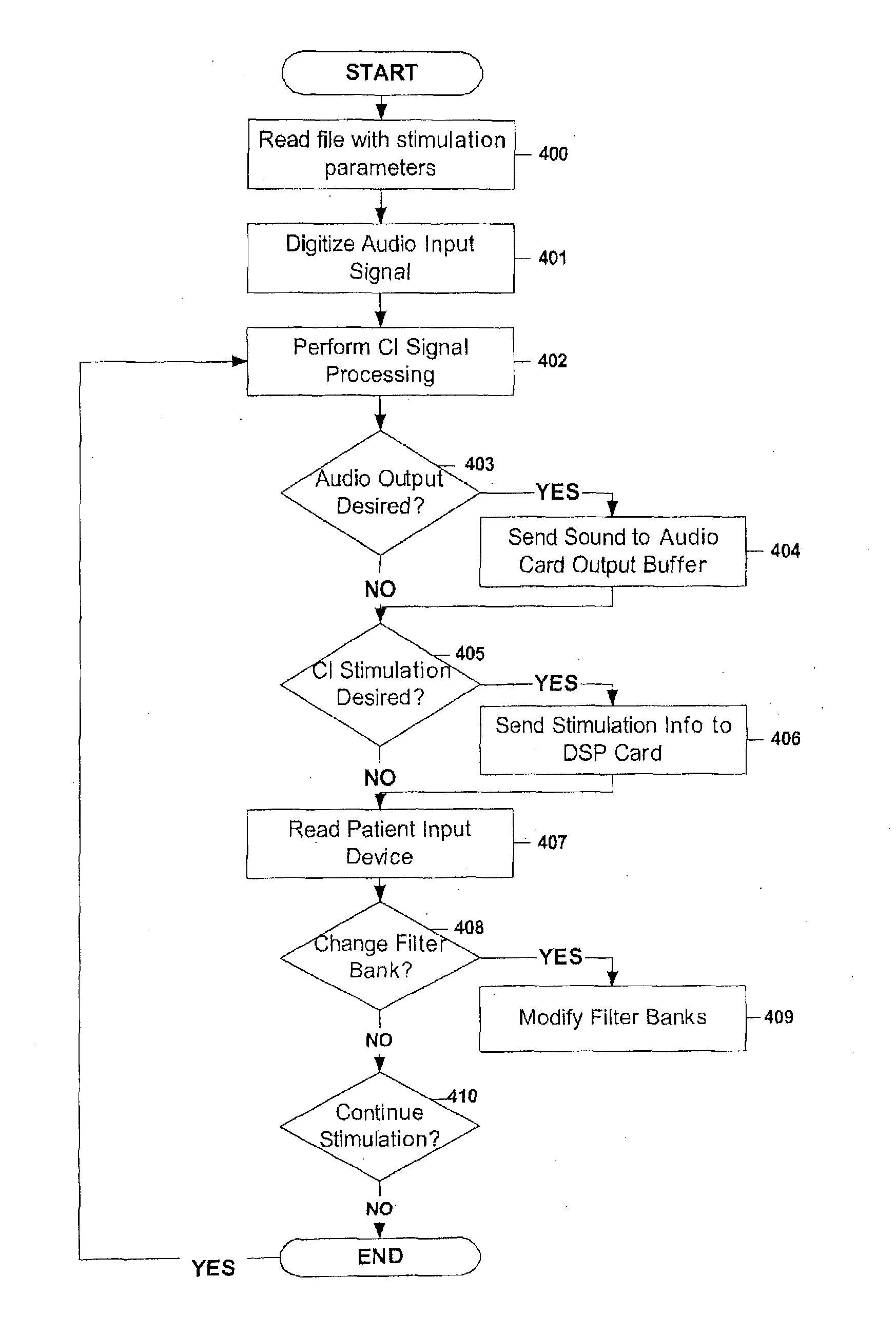
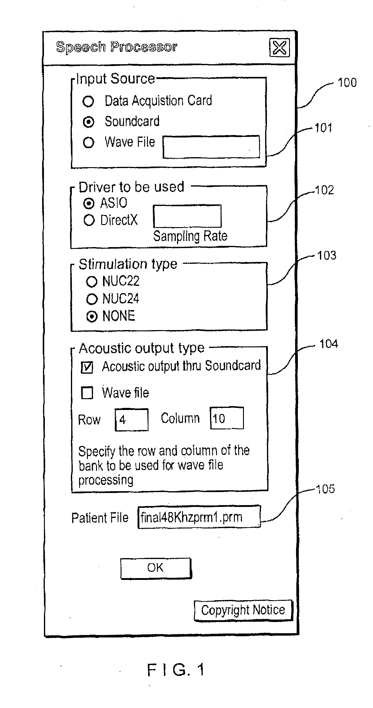
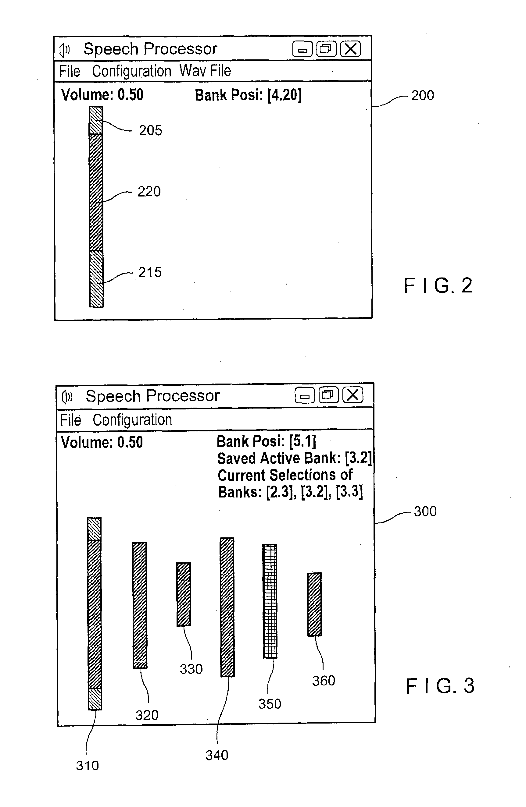
[0017]The present invention may be further understood with reference to the following description and the appended drawings. An exemplary embodiment of the present invention is directed to a system and method for providing stimulation information to a CI in real time, to facilitate the selection of a frequency-to-electrode map suited to the auditory requirements for a patient.

[0018]Under conventional CI techniques, several months are required for a patient to reach an asymptotic level of speech perception. As described above, conventional CIs distort auditory input due to frequency mismatch between the speech processor's analysis filters and the characteristic frequency of the stimulated neurons resulting from physical limitations in electrode insertion depth. In accordance with the exemplary embodiment of the present invention, a user of the CI is allowed to select a preferred frequency-to-electrode map, under the assumption that the user of the CI is best suited to select a freque...


PUM


Abstract

A system for electrically stimulating a first cochlear implant includes (a) an electrode contact simultaneously transmitting a first electrical stimulus from stimulation hardware to a first ear fitted with the first cochlear implant and a second stimulus from the stimulation hardware to a second ear, the second stimulus being one of electrical and acoustical; (b) a component establishing a plurality of frequency-to-electrode maps used to determine the first electrical stimulus; (c) a user-interface component permitting a user to adjust the frequency-to-electrode maps and receive the corresponding auditory stimulation in the first cochlear implant; (d) a component storing the frequency-to-electrode maps; and (e) a display component displaying a visual representation of multiple frequency-to-electrode maps to facilitate a comparison between the frequency-to-electrode maps in making a determination by a user of a most desired frequency-to-electrode map.

Description

PRIORITY CLAIM[0001]This application is a Continuation-in-Part application of U.S. patent application Ser. No. 13 / 046,234 filed on Mar. 11, 2011 and entitled “Cochlear Implant Fitting System”, which is a Continuation application of U.S. patent application Ser. No. 12 / 128,312 filed on May 28, 2008 entitled “Cochlear Implant Fitting System”, now U.S. Pat. No. 7,908,012, which claims the priority to the U.S. Provisional Application Ser. No. 60 / 941,053, entitled “Cochlear Implant Fitting System,” filed May 31, 2007. The specification of the above-identified applications are considered as being part of the disclosure of the present application and hereby expressly incorporated herewith by reference.FIELD OF THE INVENTION[0002]The present invention relates to a system and method for the electrical stimulation and frequency mapping of an installed cochlear implant.BACKGROUND INFORMATION[0003]Cochlear implants (“CI”s) may restore the ability to hear to deaf or partially deaf individuals by ...

Claims


Application Information

Patent Timeline
IPC IPC(8): A61N1/36
CPCA61N1/37247A61N1/36032A61N1/36039
Inventor SVIRSKY, MARIO A.
Owner NEW YORK UNIV
Learn More