
Spectral Broadening for DTS Application

a technology of spectral broadening and dts, applied in the field of noise reduction in distributed temperature sensing systems, can solve the problems of increasing operational costs, increasing operational costs, and adding to a large and expensive cable bundle, and achieves the effect of automating the crs effect and intensifying the broadening

Inactive Publication Date: 2013-08-15
HALLIBURTON ENERGY SERVICES INC
View PDF3 Cites 11 Cited by
  • Summary
  • Abstract
  • Description
  • Claims
  • Application Information

AI Technical Summary

Benefits of technology

The patent describes a system that uses a special type of fiber called a photonic crystal fiber to create a broad spectrum of light. This is achieved by passing a laser through the fiber, which causes instability, self-modulation, and four wave mixing. The system also includes attenuators and filters to control the power and spectral selection. In an improved version of the system, a second high power laser is added, which interacts with the photonic crystal fiber to further enhance the broad spectrum effect. Overall, this system has technical benefits such as reducing the CRS effect and achieving desired spectral effects.

Problems solved by technology

The resulting distributed measurement is equivalent to deploying a plurality of conventional point sensors, which would require more equipment and increase operational costs.
Each conventional electrical point sensor would require multiple electrical leads and this would add to a large and expensive cable bundle as the number of point sensors increase.
Over long distances this effect manifests itself as a noise envelope surrounding the natural Rayleigh backscattered signal that reduces the performance of any system attempting to use the signal for calculation.
As multi-wavelength Raman and Brillouin based Distributed Temperature Sensors (DTS) attempt to reach longer distances and higher accuracy, laser power has necessarily increased making CRS a commonly observed problem.

Method used


Image

  • Spectral Broadening for DTS Application
  • Spectral Broadening for DTS Application
  • Spectral Broadening for DTS Application

Examples


Embodiment Construction

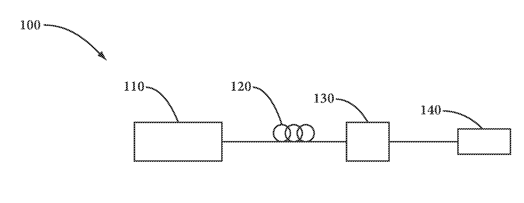
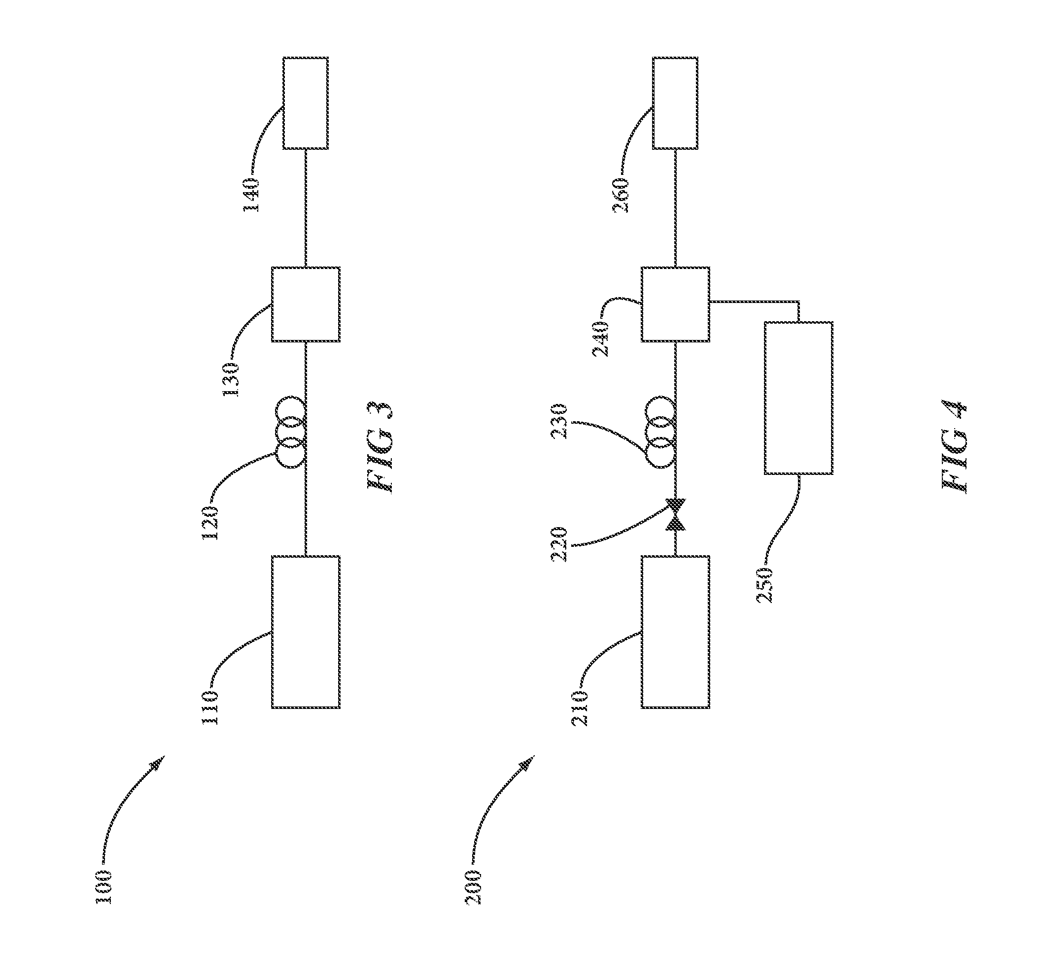
[0018]In the following detailed description, reference is made accompanying drawings that illustrate embodiments of the present invention. These embodiments are described in sufficient detail to enable a person of ordinary skill in the art to practice the invention without undue experimentation. It should be understood, however, that the embodiments and examples described herein are given by way of illustration only, and not by way of limitation. Various substitutions, modifications, additions, and rearrangements may be made without departing from the spirit of the present invention. Therefore, the description that follows is not to be taken in a limited sense, and the scope of the present invention is defined only by the appended claims.

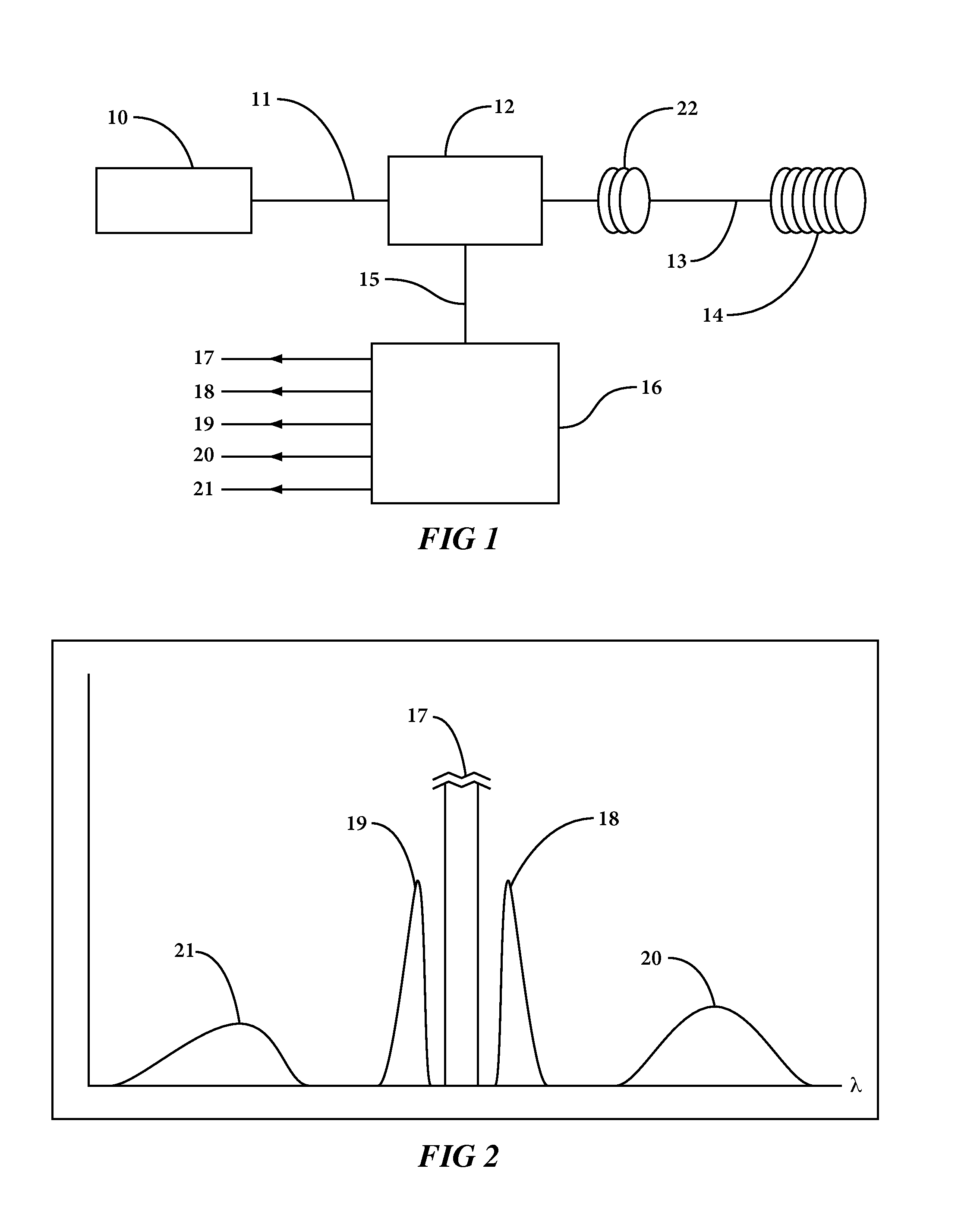
[0019]FIG. 1 illustrates a conventional DTS system, including a light source 10, a lead light fiber 11, a light splitter and combiner 12, lead fiber 13, a sensing fiber 14, optical spectrum separator 16, and a reference fiber coil 22. Light source 1...


PUM


Abstract

An apparatus and method for use in distributed temperature sensing (DTS) systems to reduce coherent Rayleigh scattering in fiber optic cables by using photonic crystal fibers.

Description

CROSS-REFERENCE TO RELATED APPLICATIONS[0001]Not applicable.STATEMENT REGARDING FEDERALLY SPONSORED RESEARCH OR DEVELOPMENT[0002]Not applicable.FIELD OF THE INVENTION[0003]The present disclosure relates to reduction of noise in distributed temperature sensing (DTS) systems.BACKGROUND OF THE INVENTION[0004]For several years, fiber optic sensors, and in particular DTS systems, have provided higher bandwidth, inherently safe operation (no generation of electric sparks), and immunity from EMI (Electromagnetic Interference) for parameter measurements.[0005]For example, the temperature profile parameter and other parameter profiles along the fiber can be monitored. The resulting distributed measurement is equivalent to deploying a plurality of conventional point sensors, which would require more equipment and increase operational costs. Each conventional electrical point sensor would require multiple electrical leads and this would add to a large and expensive cable bundle as the number o...

Claims


Application Information

Patent Timeline
IPC IPC(8): G02B6/26
CPCG01K2011/324G01D5/35387G01D5/35383G01D5/35361G01K11/32G01D5/268G01D5/353G01K11/324
Inventor MITCHELL, IAN BRADFORDJAASKELAINEN, MIKKOSAMSON, ETIENNE M.MAIDA, JR., JOHN L.
Owner HALLIBURTON ENERGY SERVICES INC
Learn More