
Electrophoresis display device and preparation method of the same

Inactive Publication Date: 2013-08-15
KOLON IND INC
View PDF5 Cites 0 Cited by
  • Summary
  • Abstract
  • Description
  • Claims
  • Application Information

AI Technical Summary

Benefits of technology

The present invention is about a new type of display that can show high-quality text with a high contrast ratio and improved visibility. The invention also includes a method for making this display.

Problems solved by technology

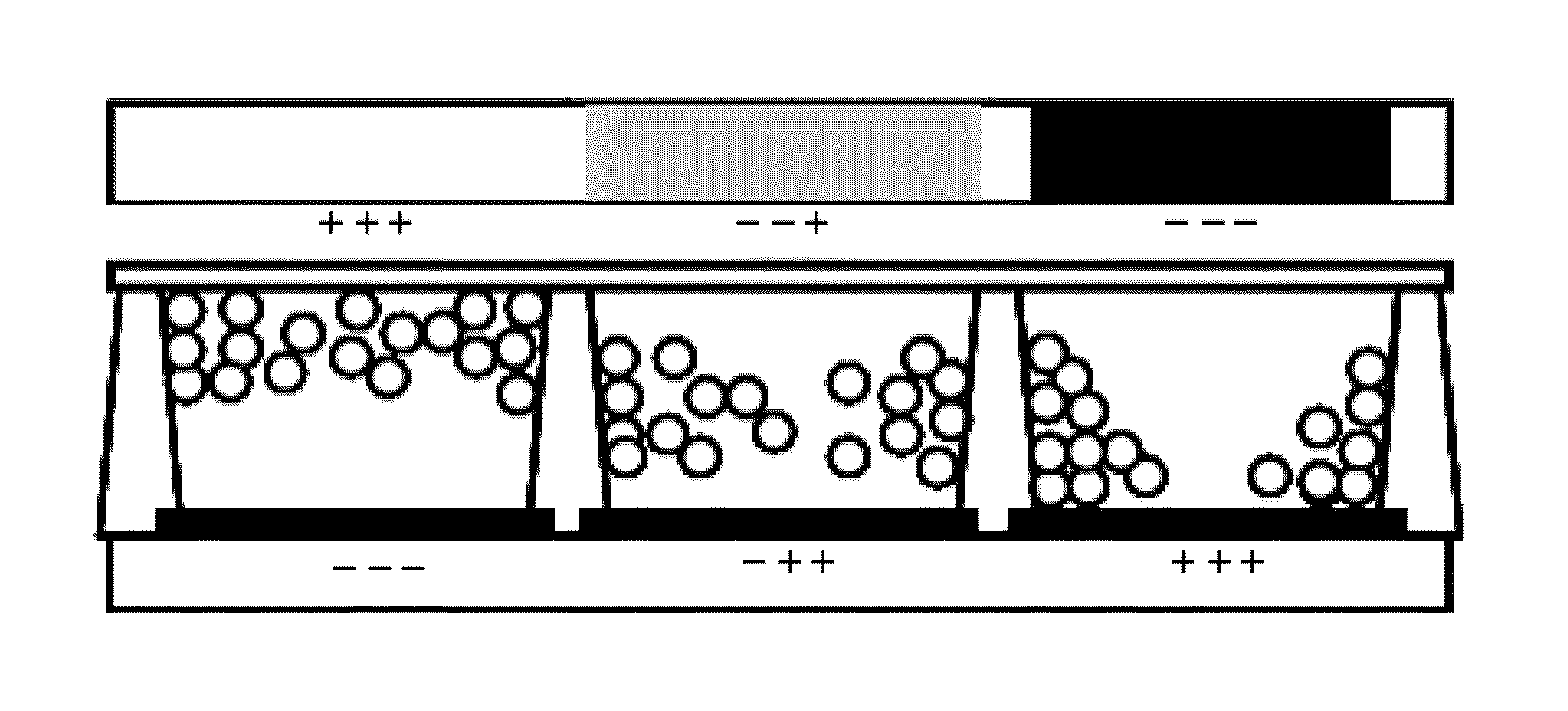
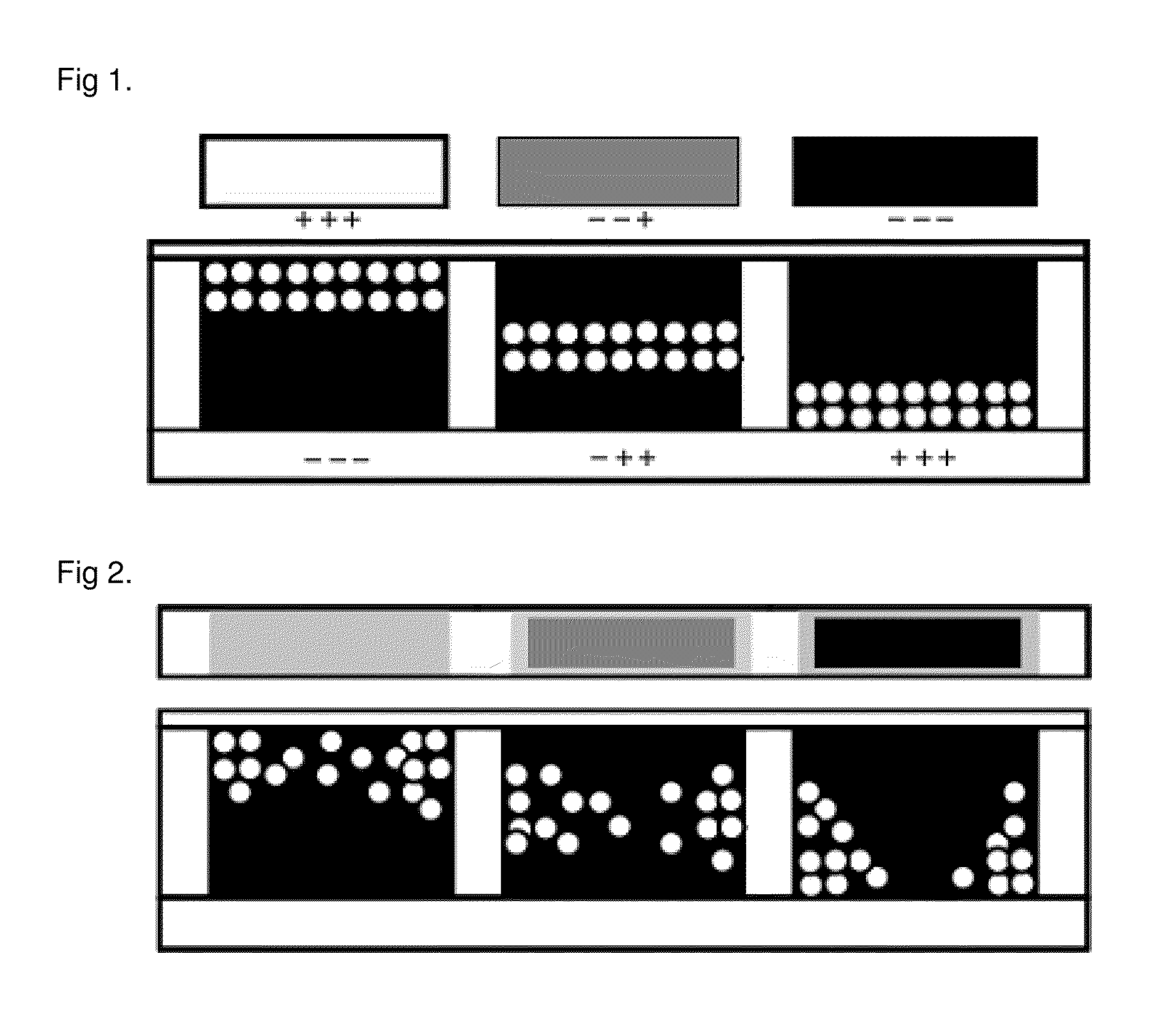
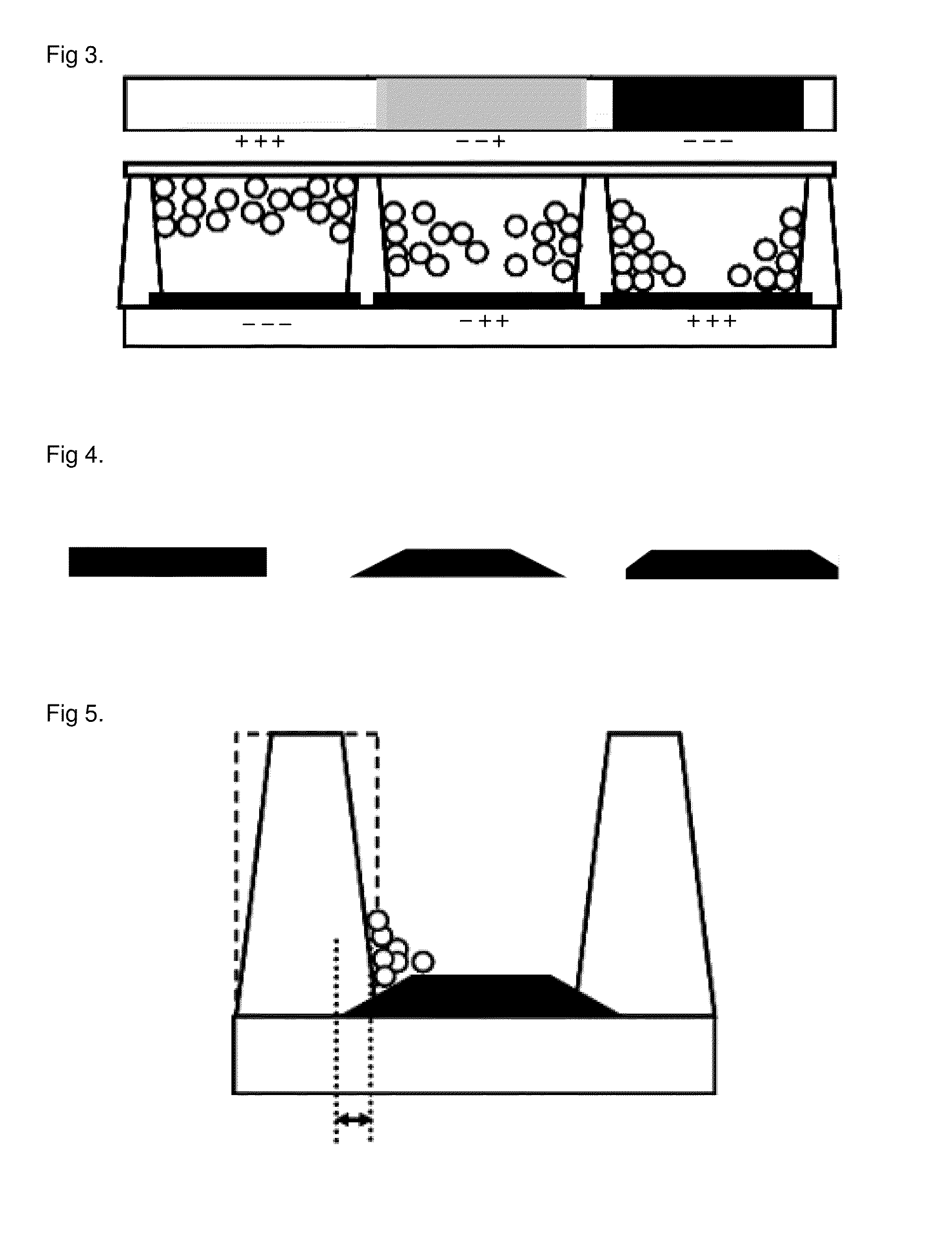
When the conventional micro-cup electrophoretic electronic paper is driven, however, the charged white particles cannot be properly positioned because of the walls of the cell or the forces of attraction which act between the particles, as shown in FIG. 2.
In consequence, the electronic paper encounters a difficulty in achieving a high contrast ratio and shows vague representation of the white and black gradient when the display is driven, resulting in poor representation of grays.
Furthermore, the micro-cup electrophoretic electronic paper has the charged white particles form a mass on the walls of the cell, consequently causing a reduced contrast ratio and poor representation of light and shade.

Method used


Image

  • Electrophoresis display device and preparation method of the same
  • Electrophoresis display device and preparation method of the same
  • Electrophoresis display device and preparation method of the same

Examples


example 1

[0066]A black photosensitive resin composition (Onlymer® BM, Kolon Industries Inc.) is spin-coated onto a PET film with an ITO electrode formed thereon and then subjected to the pre-baking, exposure, development, and post-baking processes in sequential order, to form a black pattern layer. In this regard, the spinning speed (rpm) in the spin-coating process is controlled to adjust the thickness of the black pattern layer to 0.1 μm.

[0067]A transparent acryl-based photoresist (Onlymer® BM, Kolon Industries Inc.) is spin-coated onto the ITO electrode and the black pattern layer and then subjected to the pre-baking, exposure, development, and post-baking processes in sequential order, to form a partition wall. The spinning speed (rpm) in the spin-coating process is controlled to adjust the height of the partition wall to 30 μm, and the pattern size of a photo-mask is controlled to adjust the thickness of the partition wall to 20 μm.

[0068]A mixture containing 20 g of surface-treated char...

example 2

[0070]The procedures are performed to fabricate an electrophoretic display device in the same manner as described in Example 1, except for using a slurry containing 19 g of surface-treated charged white particles (TiO2) and 81 g of a rheological fluid (3 cP) and controlling the black photosensitive resin pattern layer to have a thickness of 2.5 μm by regulating the spinning speed (rpm) in the spin-coating process.

example 3

[0071]The procedures are performed to fabricate an electrophoretic display device in the same manner as described in Example 1, except for using a slurry containing 22 g of surface-treated charged white particles (TiO2) and 78 g of a rheological fluid (3 cP) and controlling the black pattern layer to have a thickness of 5 μm by regulating the spinning speed (rpm) in the spin-coating process.


PUM

PropertyMeasurementUnit
Fractionaaaaaaaaaa
Fractionaaaaaaaaaa
Thicknessaaaaaaaaaa

Abstract

The present invention relates to an electrophoretic display device that includes: first and second substrates separated from each other by a predetermined distance; first and second electrodes formed on one side of the first and second substrates, respectively, and disposed to face each other; a black pattern layer formed on the first electrode; a plurality of partition walls formed between the first and second electrodes, one side of the partition walls on the first electrode being in contact with or overlapped with the black pattern layer; and a slurry of charged white particles filled between the partition walls. The electrophoretic display device can exhibit a high contrast ratio and enhanced visibility to realize high-quality text.

Description

FIELD OF THE INVENTION[0001]The present invention relates to an electrophoretic display device and a fabrication method thereof, and more particularly to an electrophoretic display device that exhibits a high contrast ratio and enhanced visibility to realize high-quality text, and a fabrication method thereof.BACKGROUND OF THE INVENTION[0002]Electronic paper or digital paper, also called “e-paper”, refers to an electronic device capable of being easily carried or moved and opened at any time, like paper books, newspaper, or paper magazines, and able to receive writing like ordinary paper.[0003]Electronic paper takes the form of an electrophoretic display, which holds significant advantages over the conventional flat displays, including flexibility to not be bent out of shape, a far lower production cost, and higher energy efficiency without requiring a separate backlight. Such electronic paper is very definite with a wide viewing angle and is capable of realizing a memory function s...

Claims


Application Information

Patent Timeline
IPC IPC(8): G02F1/167G02F1/1679
CPCG02F2001/1672G02F1/167G02F1/1681G02F1/1679
Inventor SONG, HO-SUKYOO, HYEON-JUNGYOON, YOUNG-SEOKANG, CHUNG-SEOCKMYOUNG, HEY-JIN
Owner KOLON IND INC
Learn More