Handheld work apparatus

a work apparatus and hand-held technology, applied in the direction of electric control, speed sensing governor, machine/engine, etc., to achieve the effect of easy speed setting

Active Publication Date: 2013-08-08
ANDREAS STIHL AG & CO KG
View PDF38 Cites 15 Cited by
  • Summary
  • Abstract
  • Description
  • Claims
  • Application Information

AI Technical Summary

Benefits of technology

[0005]It is an object of the invention to provide a handheld work apparatus of the kind described above wherein it is possible to set the speed in an easy manner.

Problems solved by technology

However, above the engagement speed, the control device takes measures to limit the speed.

Method used


Image

  • Handheld work apparatus
  • Handheld work apparatus
  • Handheld work apparatus

Examples


Embodiment Construction

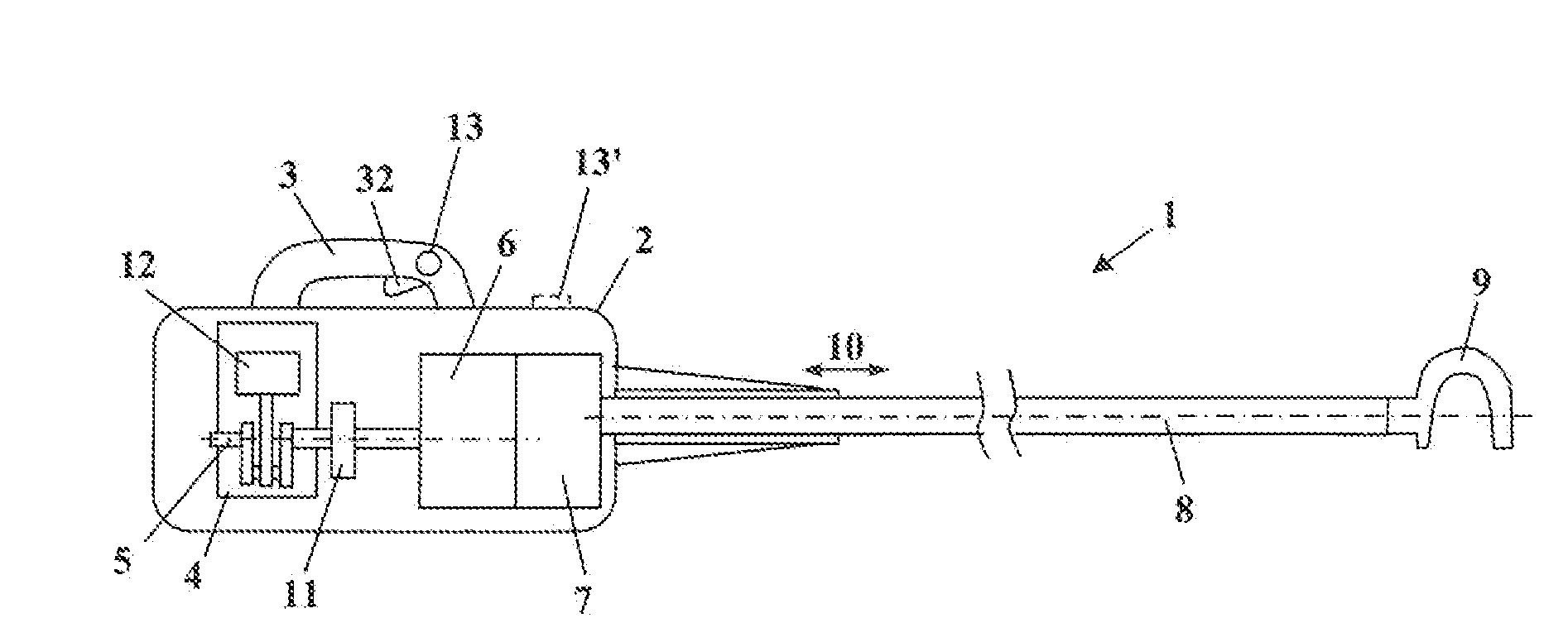
[0026]FIG. 1 shows a harvester 1, specifically an olive shaker, as an exemplary embodiment of a handheld work apparatus. However, setting the speed may also be advantageous in other handheld work apparatuses, for example in cutoff machines, brush cutters, hedge trimmers, chain saws or blowers in order to adapt to the tool in question and / or to the work assignment in question.

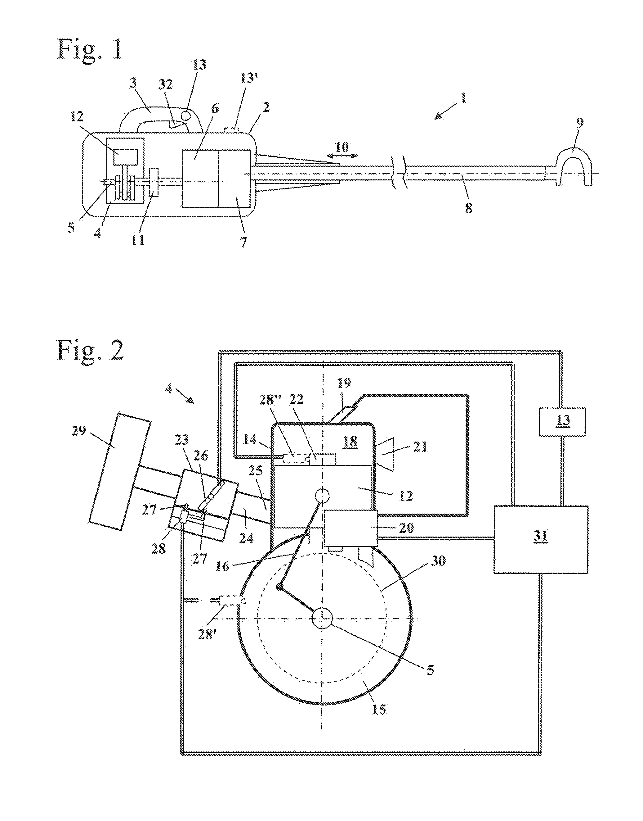
[0027]The harvester 1 has a housing 2, on which a handle 3 is arranged. Advantageously, the harvester 1 is guided during operation via the handle 3 shown and a further handle, which is not shown. A throttle lever 32 is mounted pivotably on the handle 3. Arranged in the housing 2 is a combustion engine 4, which is in the form of a two-stroke engine. However, the combustion engine 4 can also be a four-stroke engine, in particular a mixture-lubricated four-stroke engine. The combustion engine 4 is a single-cylinder engine. The combustion engine 4 has a piston 12, which drives a crankshaft 5 in rotation. The cranksh...


PUM


Abstract

A handheld work apparatus has a combustion engine (4) for driving a tool. The combustion engine (4) has an ignition device, a device for metering fuel and a control device (31). The control device (31) engages when an engagement speed (nE1, nE2) is reached, in order to limit the speed (n) of the combustion engine (4). In order to allow the speed (n) to be set in an easy manner at full throttle, the work apparatus has a device for setting the engagement speed (nE2) by the user.

Description

CROSS REFERENCE TO RELATED APPLICATION[0001]This application claims priority of German patent application no. 10 2012 002 225.5, filed Feb. 4, 2012, the entire content of which is incorporated herein by reference.FIELD OF THE INVENTION[0002]The invention relates to a handheld work apparatus having a combustion engine for driving a tool. The combustion engine includes an ignition device, a fuel-metering device and a control unit. The control unit intervenes when the combustion, engine reaches an engagement rotational speed to limit the rotational speed of the engine.BACKGROUND OF THE INVENTION[0003]U.S. Pat. No. 8,322,326 discloses a combustion engine for a handheld work apparatus, wherein the speed is limited when an engagement speed is reached.[0004]In handheld work apparatuses, continuous operation with a reduced speed, that is to say a speed below the full load speed, can be advantageous. This is the case for example in harvesters, in which it is advantageous to set the speed dep...

Claims


Application Information

Patent Timeline
Patent Type & Authority Applications(United States)
IPC IPC(8): F02D31/00
CPCF02D41/0087F02D31/00F02P5/1502F02P9/005F02D31/001Y02T10/46F02D31/009F02D37/02F02D2200/602F02D2200/604F02D2400/06F02D31/006F02D41/2432A01D46/26A01D2046/266Y02T10/40
Inventor DANGELMAIER, MANUELGEGG, TIM
Owner ANDREAS STIHL AG & CO KG
Why Eureka
Try Eureka