Wind turbine rotor blade lightning discharger and wind turbine generator equipped with the same

a technology of lightning discharger and wind turbine, which is applied in the direction of boats, marine propulsion, chairs, etc., can solve the problems of increasing the risk of lightning hitting parts other than the receptors provided at the tip of the blade, the risk of damage to the wind turbine blade, and annoying fluid noise, so as to improve the lightning resistance and improve the lightning resistance. , the effect of simple structur

Inactive Publication Date: 2013-08-01
MITSUBISHI HEAVY IND LTD
View PDF6 Cites 9 Cited by
  • Summary
  • Abstract
  • Description
  • Claims
  • Application Information

AI Technical Summary

Benefits of technology

The invention is a wind turbine blade that can protect against lightning without adding extra noise or complexity. It has a simple design that improves resistance without needing additional equipment. This makes it easier to use and maintain. The invention is also useful for wind turbine generators that need to minimize the impact of lightning on their performance.

Problems solved by technology

By providing such receptors, it is possible to quite reliably prevent lightning striking the tips of the blades; however, when lightning strikes a position shifted to the blade root side by a distance of several meters from the blade tip, the lightning current may destroy the outer skin of the blade and reach the interior of the blade, causing a risk of damage to the wind turbine blade.
In future, with the increasing size of wind turbine generators, there will be a trend towards larger and larger blades, and in regions close to the shore, because the lightning attachment rate is lower overall due to the build up of salt compounds on the blade surfaces, there is a trend towards a greater risk of lightning striking parts other than the receptors provided at the tips of the blades.
However, when numerous diverter strips are disposed on the surface of the wind turbine blade as described above, because of the diverter strips which project from the surface of the wind turbine blade, when the wind turbine rotor blade rotates, Karman vortices (or Karman vortex streets) are generated on the downstream side of the diverter strips with respect to the airflow flowing at the surface of the wind turbine blade, and this causes annoying fluid noise.
Doing so, however, reduces the lightning attachment performance of the diverter strips and their ability to transmit the lightning current, and depressions for embedding the diverter strips are inevitably produced in the surface of the wind turbine blade, which leads to force concentration in the periphery of these depressions, thus causing a decrease in strength of the wind turbine blade.

Method used


Image

  • Wind turbine rotor blade lightning discharger and wind turbine generator equipped with the same
  • Wind turbine rotor blade lightning discharger and wind turbine generator equipped with the same
  • Wind turbine rotor blade lightning discharger and wind turbine generator equipped with the same

Examples


first embodiment

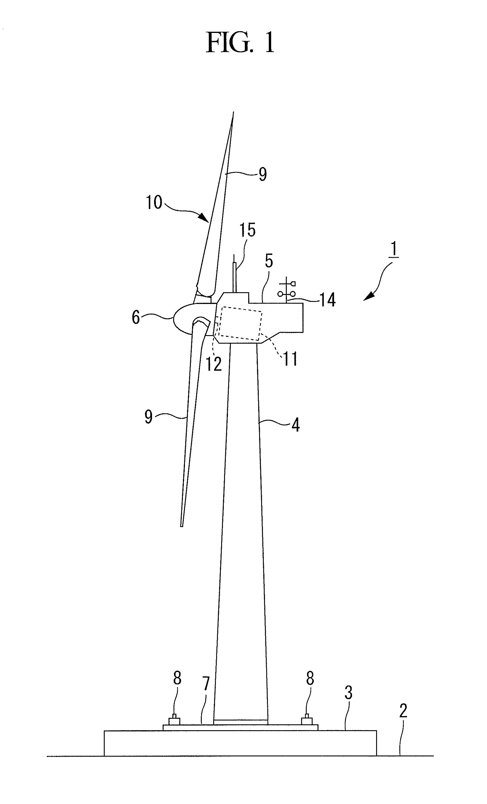
[0040]FIG. 1 is a side view of an example of a wind turbine generator in which a wind turbine rotor blade lightning discharger according to the present invention can be employed. This wind turbine generator 1 includes, for example, a tower 4 erected on a reinforced-concrete base 3 disposed on the ground 2, a nacelle 5 disposed at the top end of the tower 4, and a rotor head 6 supported on the front end of the nacelle 5 so as to be freely rotatable around a rotor shaft in an approximately horizontal transverse direction.

[0041]The tower 4 is of a steel-tube monopole construction. A baseplate 7 made of, for example, steel plate, is secured to the bottom end of the tower 4, and this baseplate 7 is securely fastened to the base 3 with a number of anchor bolts 8. A plurality of (e.g., three) radially extending wind turbine blades 9 are attached to the rotor head 6 to form a wind turbine rotor blade 10, a generator 11 is accommodated inside the nacelle 5, and a rotor shaft 12 of the rotor ...

second embodiment

[0056]FIG. 6 is a diagram showing a second embodiment of a lightning discharger according to the present invention.

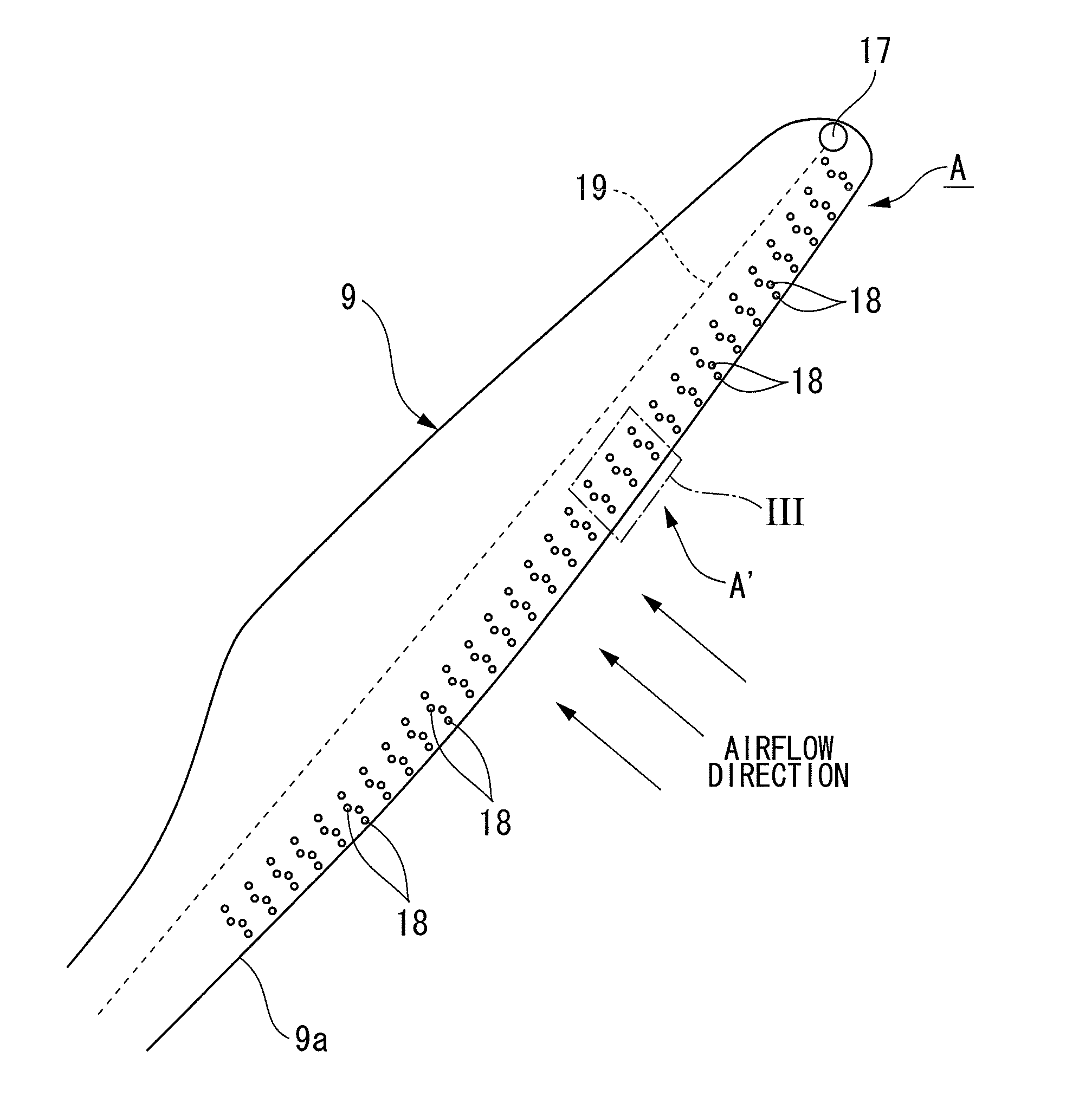
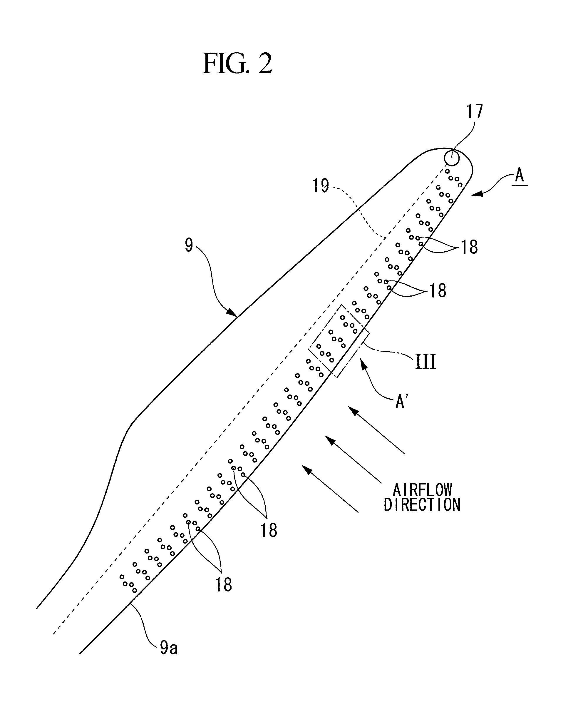
[0057]In a noise suppressing structure B′ of a lightning discharger B in this second embodiment, the diverter strips 18 serving as the plurality of lightning discharge members provided on the surface of the wind turbine blade 9 form groups G2 each composed of, for example, three diverter strips 18, and a plurality of these groups G2 are arranged along the longitudinal direction of the wind turbine blade 9. The individual groups G2 are arrayed in close proximity to the leading edge of the wind turbine blade 9, similarly to the groups G1 of diverter strips 18 in the first embodiment.

[0058]In each group G2, three disc-shaped (button-shaped) diverter strips 18e, 18f, and 18g are arrayed in a meandering fashion along the flow direction of the airflow that flows at the surface of the wind turbine blade 9. The spacing between these three diverter strips 18e, 18f, and 18g is se...

third embodiment

[0060]FIG. 7 is a diagram showing a third embodiment of a lightning discharger according to the present invention.

[0061]In a noise suppressing structure C′ of a lightning discharger C in this third embodiment, the diverter strips 18 serving as the plurality of discharger members provided on the surface of the wind turbine blade 9 form groups G3 each composed of, for example, four diverter strips 18, and a plurality of these groups G3 are arranged along the longitudinal direction of the wind turbine blade 9. The individual groups G3 are arranged in close proximity to the leading edge of the wind turbine blade 9.

[0062]A plurality of diverter strips 18h, 18i, 18j, and 18k in each group G3 are disc shapes (button shapes) of the same size; however, they may have different sizes, like the second embodiment, or different shapes. Then, spacings S1, S2, and S3 between these diverter strips 18h to 18k are set to be nonuniform, for example, satisfying S213.

[0063]With this kind of noise suppres...


PUM


Abstract

By means of a simple structure, lightning resistance is improved without increasing the level of fluid noise due to a lightning discharge member provided on a surface of a wind turbine blade. A wind turbine rotor blade lightning discharger, in which a diverter strip serving as a lightning discharge member protrudes from a surface of a wind turbine blade that extends in a radial direction from a rotor head supported in a freely rotatable manner, includes a noise suppressing structure that suppresses the generation of a Karman vortex, which causes noise, on the downstream side of the diverter strip with respect to an airflow that flows at the surface of the wind turbine blade during rotation of the wind turbine rotor blade.

Description

CROSS-REFERENCE TO RELATED APPLICATIONS[0001]This application is based on Japanese Patent Application No. 2010-267716, the contents of which are incorporated herein by reference.BACKGROUND OF THE INVENTION[0002]1. Field of the Invention[0003]The present invention concerns a wind turbine rotor blade in which a lightning discharge member is provided so as to protrude from the surface of a wind turbine blade, and in particular relates to a wind turbine rotor blade lightning discharger that is designed to suppress noise that the lightning discharge member generates and to a wind turbine generator equipped with the same.[0004]2. Description of Related Art[0005]Standard wind turbine generators are equipped with a wind turbine rotor blade having several wind turbine blades that extend in radial directions centered on a rotor head and have a configuration in which the rotor head is supported, at a shaft thereof, by a nacelle that is supported at the top of a tower so as to be capable of tur...

Claims


Application Information

Patent Timeline
Patent Type & Authority Applications(United States)
IPC IPC(8): F03D11/00
CPCY02E10/722F03D11/0033F03D80/30Y02E10/72
Inventor HAYASHI, KENTARONAKA, TAKEHIROKIMURA, MUSASHI
Owner MITSUBISHI HEAVY IND LTD
Why Eureka
Try Eureka