
Graphene-drum pump and engine systems

a graphene-drum pump and graphene-drum technology, which is applied in the direction of machines/engines, flexible member pumps, positive displacement liquid engines, etc., can solve the problems of slow pump speed, najafi patent-fabricated microvacuum pump assembly cannot maintain a high vacuum on one side, and requires a relatively high voltage to opera

Inactive Publication Date: 2013-08-01
BRANE AUDIO LLC
View PDF3 Cites 0 Cited by
  • Summary
  • Abstract
  • Description
  • Claims
  • Application Information

AI Technical Summary

Benefits of technology

The patent describes a valve that includes a protective coating made of graphene oxide and tungsten to prevent damage from oxidation and corrosive fluids. The coating is very thin, less than 5 nm, and acts as a barrier to protect the valve. The valve also includes a non-conductive member to prevent the membrane from touching the gate and causing a short circuit. The predetermined distance between the membrane and the gate is small enough to prevent most molecules of fluid from flowing through, but big enough to avoid wear and tear on the valve.

Problems solved by technology

Accordingly, the pump assembly is limited to kHz operation (resulting in slow pump speed) and requires a relatively high voltage to actuate (to overcome the inertia and stiffness of a thick diaphragm).
It is believed that, unlike graphene drums and other atomically thin, electrically conductive drums, the MEMS-fabricated microvacuum pump assembly of the Najafi Patent cannot maintain a high vacuum on one side.
This would be disadvantageous because a vacuum enables a high electric field (and, thus, a high actuation force, between the gate and the diaphragm without arcing).
The Najafi Patent also appears to be a high wear device because the pump and valve membranes of the MEMS-fabricated microvacuum pump assembly require repeated physical contact with other parts of the pump assembly to operate properly.

Method used


Image

  • Graphene-drum pump and engine systems
  • Graphene-drum pump and engine systems
  • Graphene-drum pump and engine systems

Examples


Embodiment Construction

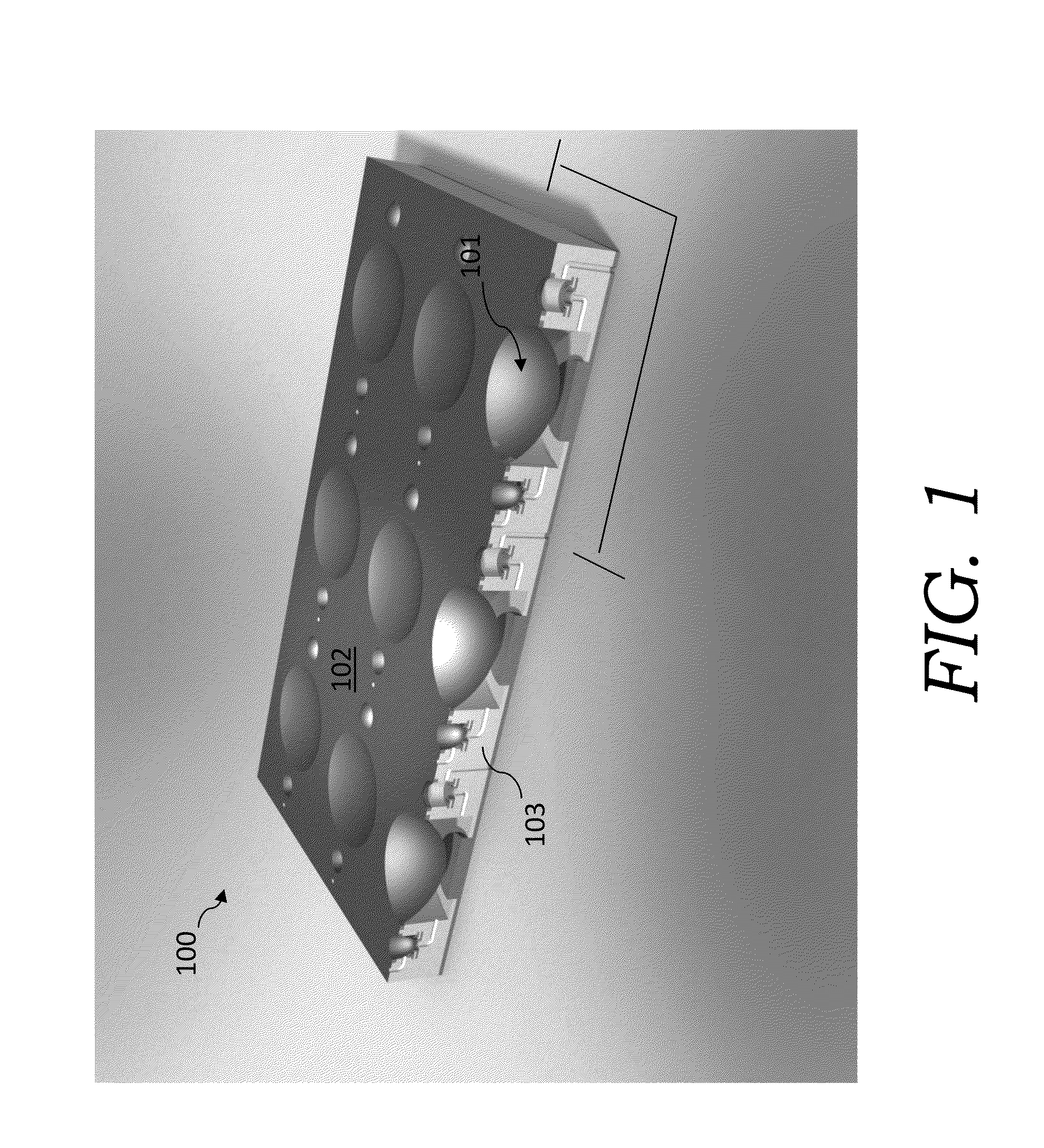
[0107]In an embodiment of the present invention, one or more graphene drums can be utilized in a pump system. FIG. 1 depicts a graphene-drum pump system 100 that has an array of graphene-drum pumps 101 (as illustrated there are nine graphene pumps 101 in FIG. 1). As oriented in FIG. 1, the top layer 102 is graphene. The top layer is mounted on an insulating material 103 (such as silicon dioxide).

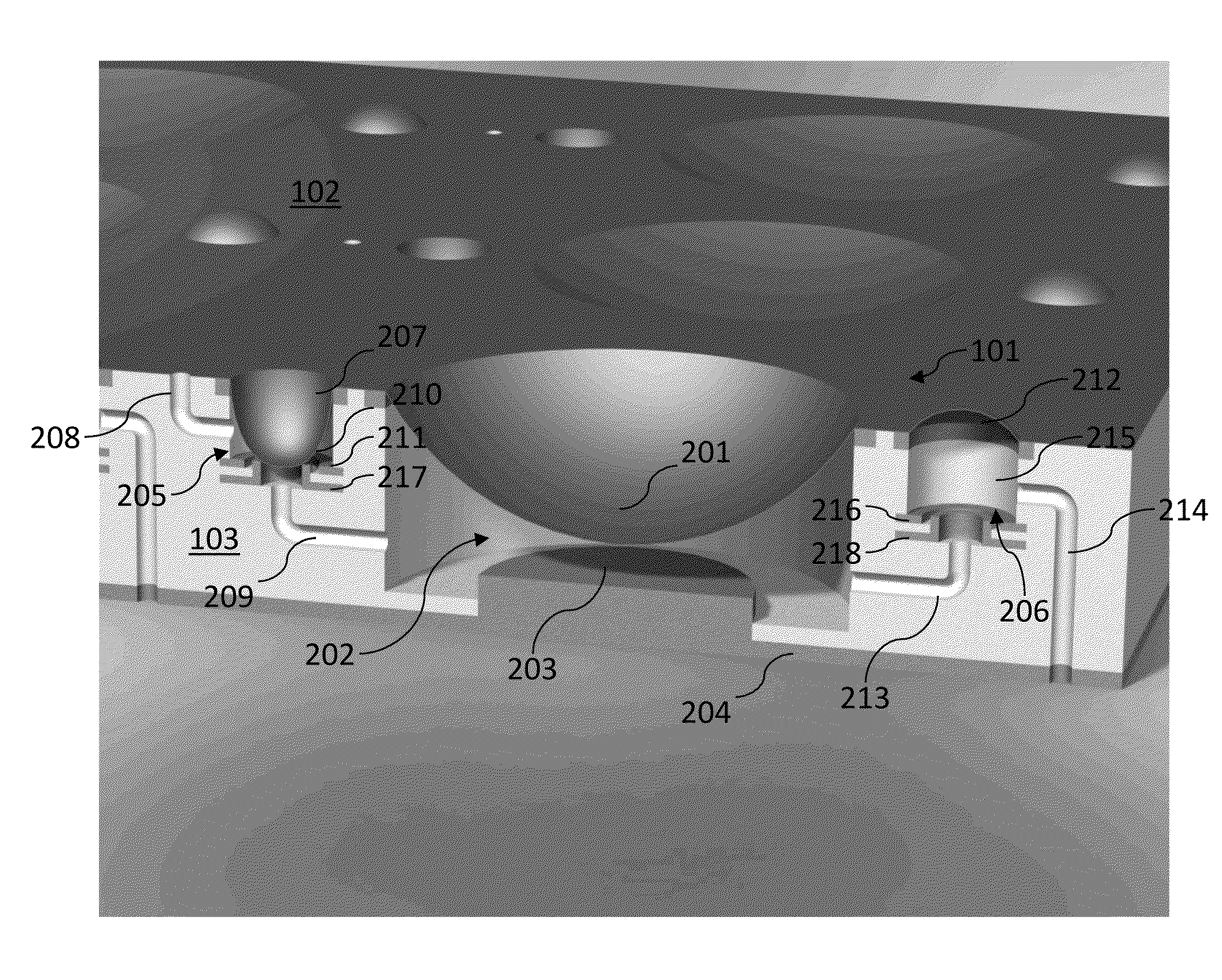
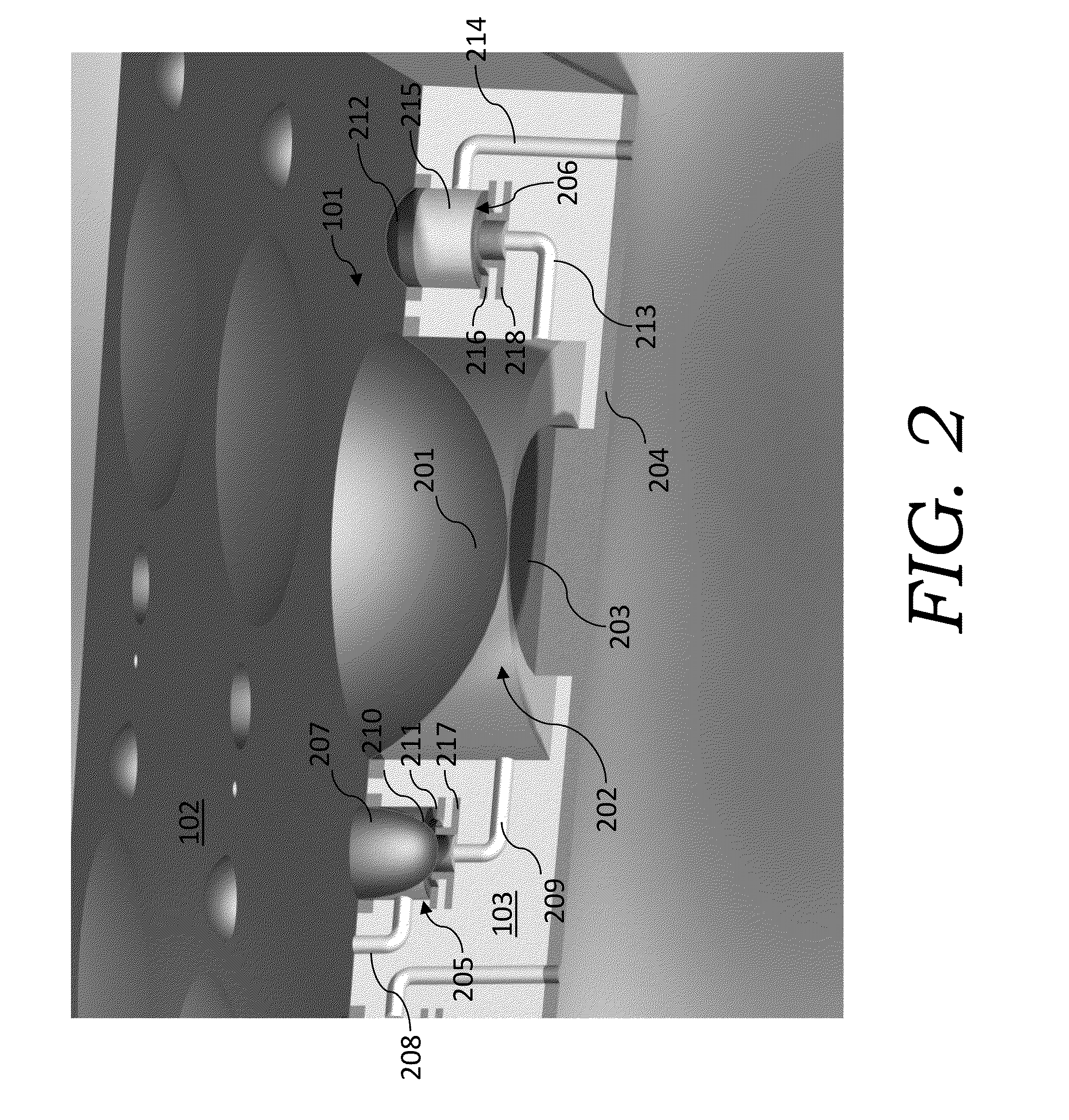
[0108]FIG. 2 depicts a close-up of a graphene-drum pump 101 in the graphene-drum pump system 100 of FIG. 1. Graphene-drum pump 101 utilizes a graphene drum as the main diaphragm (main diaphragm graphene drum 201). The main diaphragm seals a boundary of the cavity 202 of the graphene-drum pump 101. The cavity is also bounded by insulating material 103 and a metallic gate 203 (which is a metal such as tungsten). The metallic gate 203 is operatively connected to a voltage source (not shown), such as by a metallic trace 204. The main diaphragm graphene drum 201 can be designed to operate in a ma...


PUM


Abstract

The present invention relates to pump systems and engine systems having graphene drums. In embodiments of the invention, the graphene drum can be utilized in the main chambers and / or valves of the pumps and engines.

Description

CROSS-REFERENCE TO RELATED PATENT APPLICATIONS[0001]This application claims priority to: provisional U.S. Patent Application Ser. No. 61 / 301,209, filed on Feb. 4, 2010, entitled “Graphene-Drum Pump and Engine Systems,” which provisional patent application is each commonly assigned to the Assignee of the present invention and is hereby incorporated herein by reference in its entirety for all purposes.TECHNICAL FIELD[0002]The present invention relates to pump systems and engine systems having graphene drums.SUMMARY OF THE INVENTION[0003]Graphene membranes (also otherwise referred to as “graphene drums”) have been manufactured using process such as disclosed in Lee et al. Science, 2008, 321, 385-388. PCT Patent Appl. No. PCT / US09 / 59266 (Pinkerton) (the “PCT US09 / 59266 Application”) described tunneling current switch assemblies having graphene drums (which graphene drums generally having a diameter between about 500 nm and about 1500 nm). As described in the PCT US09 / 59266 Application, ...

Claims


Application Information

Patent Timeline
Patent Type & Authority Applications(United States)
IPC IPC(8): F04B43/00
CPCF04B43/043F16K99/0001F16K99/0015F04B45/04F16K2099/0094F16K2099/0096F04B43/0009F16K99/0051
Inventor PINKERTON, JOSEPH F.
Owner BRANE AUDIO LLC
Learn More