
Selective fracture face dissolution

a fracture face and selective technology, applied in the direction of fluid removal, borehole/well accessories, chemistry apparatus and processes, etc., can solve the problems of acid corrosion creating iron compounds such as iron chlorides, strong acids corroding such materials, and affecting the stability or effectiveness of other components

Inactive Publication Date: 2013-08-01
BROWN J ERNEST +1
View PDF6 Cites 18 Cited by
  • Summary
  • Abstract
  • Description
  • Claims
  • Application Information

AI Technical Summary

Benefits of technology

This method reduces acid consumption, minimizes corrosion, and enhances differential etching, creating highly conductive fractures while protecting certain areas from acid reaction, thus improving the effectiveness and safety of acid fracturing treatments.

Problems solved by technology

There are generally three major problems encountered during this normal procedure.
First, in the pumping operation the acid is in contact with iron-containing components of the wellbore such as casing, liner, coiled tubing, etc.
Strong acids are corrosive to such materials, especially at high temperature.
Furthermore, acid corrosion creates iron compounds such as iron chlorides.
These iron compounds may precipitate, especially if sulfur or sulfides are present, and may interfere with the stability or effectiveness of other components of the fluid, thus requiring addition of iron control agents or iron sequestering agents to the fluid.
Second, if, as is usually the case, the intention is to use the acid to treat parts of the formation at a significant distance away from the wellbore (usually in addition to treating parts of the formation nearer the wellbore), this may be very difficult to accomplish because if an acid is injected from the surface down a wellbore and into contact with the formation, the acid will naturally react with the first reactive material with which it comes into contact.
At best this may be wasteful of acid; at worst this may make the treatment ineffective or even harmful.
In general, the higher the temperature the more reactive is the acid and the greater are the problems.
This is usually a severe problem when at least some of the formation is carbonate, which is typically very reactive towards acid.
Third, even when the acid has successfully been contacted with the desired region of the fracture face, there is sometimes a tendency for the acid to react evenly with the fracture faces, especially in localized regions, so that conductive channels along the fracture faces are not created by differential etching in such regions after fracture closure.
There are problems with these methods.
Although emulsified acids are popular and effective, they require additional additives and specialized equipment and expertise, and may be difficult to control.
A problem with the encapsulated acids is that the location and timing of release of the acid may be difficult to control.
Physical damage to the encapsulating material, or incomplete or inadequate coating during manufacture, could cause premature release of the acid.

Method used


Image

  • Selective fracture face dissolution
  • Selective fracture face dissolution

Examples


example 1

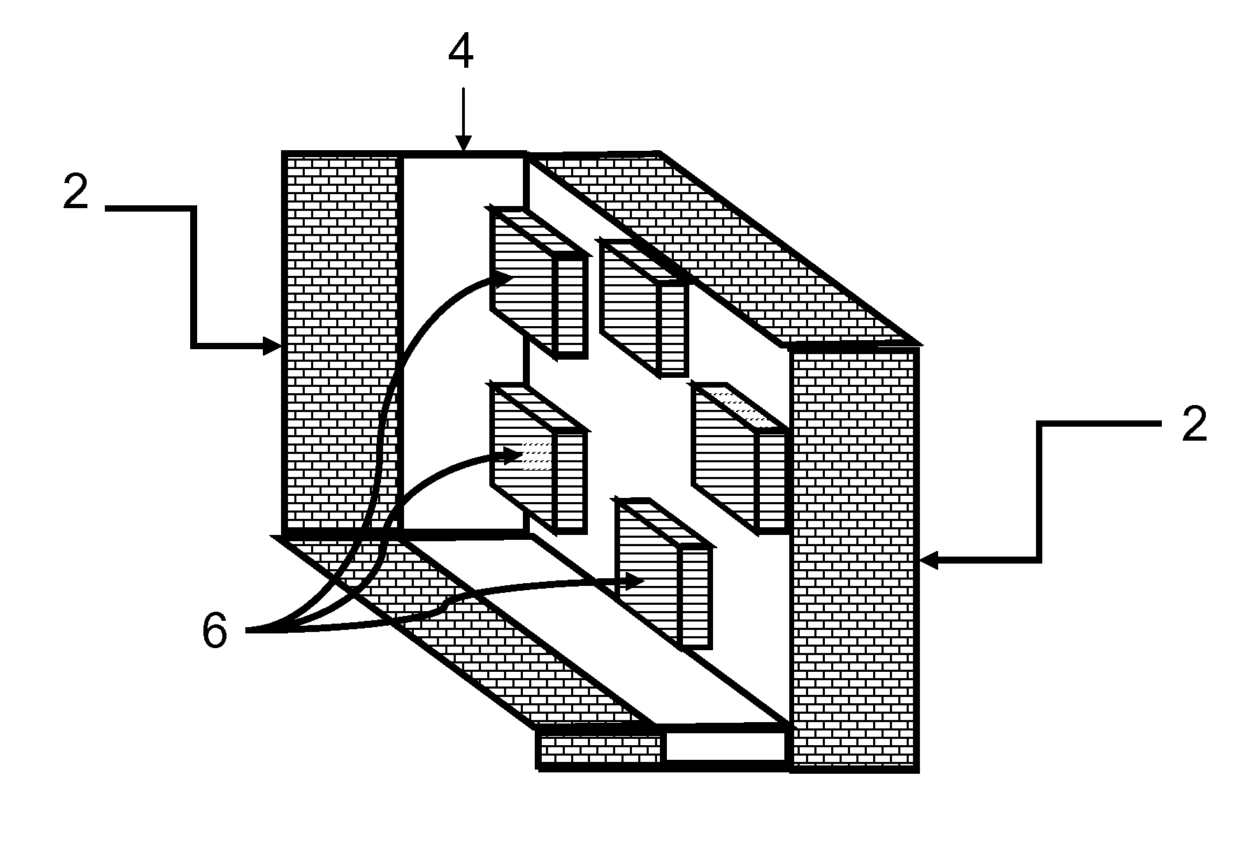
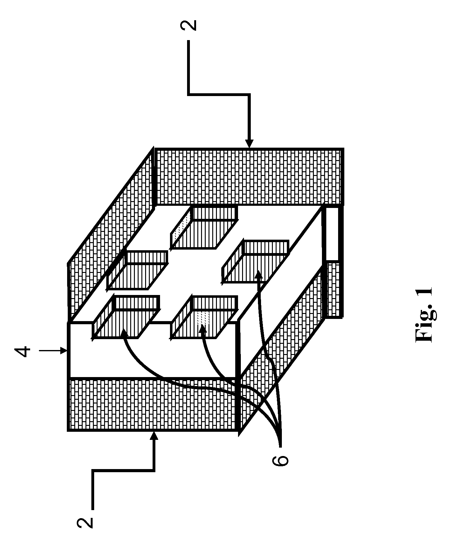
[0042]FIG. 1 shows a schematic of how a fracture would appear if created by the method of the invention. The fracture [4] in the formation [2] contains regions [6] that are not open to fluid flow. These regions are where the inert or reactive masking material is trapped when the fracture closes. The fracture face is protected from the formation dissolving agent at those locations.

example 2

[0043]A) The following is a representative job design that would be used for a typical treatment with a mixture of solid acid precursor fibers and solid acid precursor beads. The base fluid is 2.4 g / L of zirconium crosslinked CMHPG.

Solid AcidSolid AcidSolid AcidSolid AcidStagePrecursorPrecursorPrecursorPrecursorRateVolumeBeadsBeadsFiberFiberStagekL / minBase FluidkLkg / Lkgg / LkgPAD3.98Z-CMHPG159000013.98Z-CMHPG11.40.066802.42723.98Z-CMHPG11.40.1213612.42733.98Z-CMHPG11.40.1820414.85443.98Z-CMHPG11.40.2427224.85453.98Z-CMHPG11.40.3034027.28263.98Z-CMHPG11.40.3640827.28273.98Z-CMHPG11.40.4247639.610983.98Z-CMHPG11.40.4854439.6109FLUSH3.98Water46.50000[0044]B) The following is a representative job design that would be used for a typical treatment with solid acid precursor beads and an inert masking material. The base fluid is 4.2 g / L of guar crosslinked with boric acid.

Solid AcidSolid AcidInertInertStagePrecursorPrecursorMaskingMaskingRateVolumeBeadsBeadsMaterialMaterialStagekL / minBase Flu...

example 3

[0046]A pack that was a mixture of polylactic acid beads and rubber pellets was sandwiched between the ends of two carbonate cores. Both cores were saturated with 2% KCl brine and a small amount of water was added to the pack to reduce the amount of air trapped in the pack. The complete combination of pack and cores was then heated to 135° C. for 4 hours. Upon disassembly, and inspection of the surface of the cores, it was seen that there were areas where the rubber pellets had agglomerated; these areas were not etched but the remainder of the surface was etched.


PUM


Abstract

A method is given for acid fracturing a subterranean formation for improving the flow of fluids. The principal source, optionally the sole source, of the acid is a solid acid-precursor, optionally injected with an additional solid that is inert and that masks a portion of the newly created fracture faces so that the fracture face etching by the acid is not uniform. The method ensures a good flow path for fluids between the fracture tip and the wellbore.

Description

CROSS REFERENCE TO RELATED APPLICATIONS[0001]This application is a continuation application of U.S. patent application Ser. No. 10 / 941,384, filed on Sep. 15, 2004, which claims the benefit of U.S. patent application Ser. No. 10 / 605,784, filed on Oct. 27, 2003, now U.S. Pat. No. 7,166,560, which claimed the benefit of U.S. Provisional Patent Application No. 60 / 421,696, filed on Oct. 28, 2002. This application is related to U.S. patent application Ser. No. 10 / 941,385, entitled “Differential Etching in Acid Fracturing,” filed Sep. 15, 2004, now abandoned inventors J. Ernest Brown, et al., U.S. patent application Ser. No. 10 / 941,355, entitled “Solid Sandstone Dissolver,” filed Sep. 15, 2004, now abandoned, inventors J. Ernest Brown, et al., and U.S. patent application Ser. No. 11 / 858,266, which is a divisional application of U.S. patent application Ser. No. 10 / 941,355, entitled “Solid Sandstone Dissolver,” filed Sep. 20, 2007, now U.S. Pat. No. 7,540,328.BACKGROUND OF THE INVENTION[0002...

Claims


Application Information

Patent Timeline
Patent Type & Authority Applications(United States)
IPC IPC(8): E21B43/26
CPCC09K8/68E21B43/26C09K8/74C09K8/72E21B43/27
Inventor BROWN, J. ERNESTSTILL, JOHN W.
Owner BROWN J ERNEST
Learn More