Device for detecting breakage of a diaphragm in a hydraulically-actuated pump, a method of mounting such a device on a pump, and a pump fitted with such a device

a technology of hydraulically actuated pumps and devices, which is applied in the direction of flexible member pumps, machines/engines, positive displacement liquid engines, etc., can solve the problems of deteriorating pump performance, thin diaphragms not always perfectly fitted on the intermediate diaphragms, and affecting the performance of the pump

Inactive Publication Date: 2013-07-18
MILTON ROY EURO
View PDF7 Cites 0 Cited by
  • Summary
  • Abstract
  • Description
  • Claims
  • Application Information

AI Technical Summary

Benefits of technology

[0024]As a result, once the above-described first and second steps have been performed, the second portion of the piston is withdrawn and the first portion of the piston is lowered to the level of the second chamber. The free ball of the check valve is then inserted in the hole in the first portion so as to come naturally into position on the seat of the check valve. The second portion of the piston is then arranged on the first portion so as to close the end of the piston. The piston is then raised until it co-operates in leakt

Problems solved by technology

Nevertheless, it is found that the thin diaphragms are not always perfectly fitted on the intermediate diaphragm.
Unfortunately, the presence of air in the space between each thin diaphragm and the intermediate diaphragm greatly degrades the perf

Method used


Image

  • Device for detecting breakage of a diaphragm in a hydraulically-actuated pump, a method of mounting such a device on a pump, and a pump fitted with such a device
  • Device for detecting breakage of a diaphragm in a hydraulically-actuated pump, a method of mounting such a device on a pump, and a pump fitted with such a device
  • Device for detecting breakage of a diaphragm in a hydraulically-actuated pump, a method of mounting such a device on a pump, and a pump fitted with such a device

Examples


Embodiment Construction

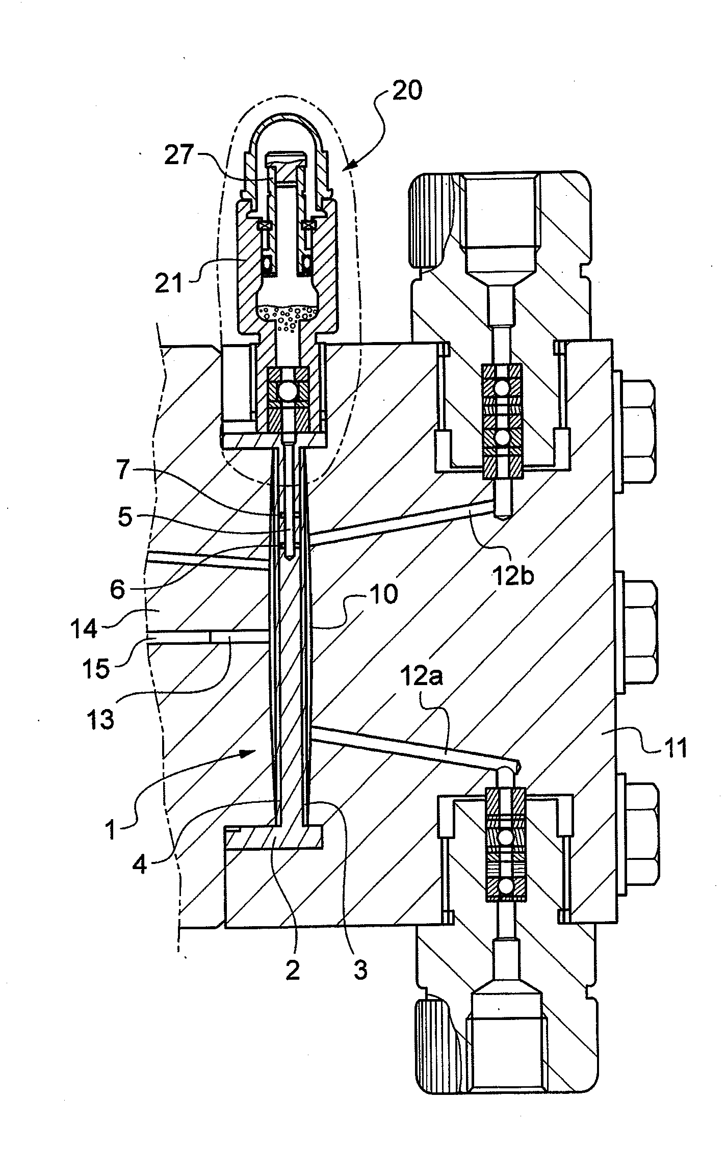
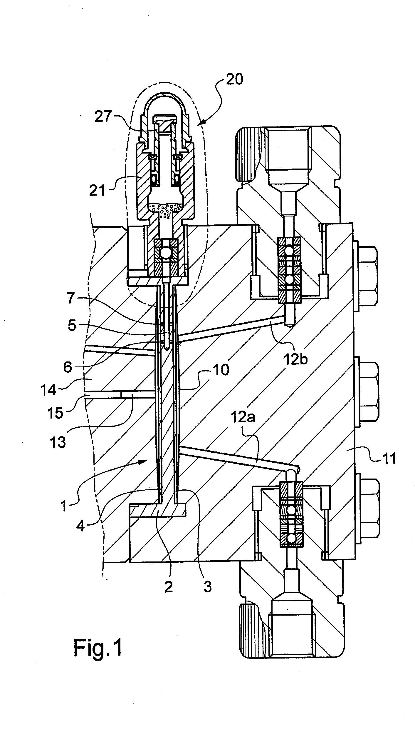
[0036]With reference to FIG. 1, the hydraulically-actuated pump in this example has a composite diaphragm 1 that comprises an intermediate diaphragm 2 between a first thin diaphragm 3 and a second thin diaphragm 4. The intermediate diaphragm 2 is thick and in the form of an elastically deformable dome. The pump has a duct 5 that is arranged in the thickness of the intermediate diaphragm 2 and has a first end opening to the outside of the pump and a second end connected to at least one drain channel. In this example, the second end is connected to a first drain channel 6 and to a second drain channel V. Each drain channel is also provided in the thickness of the intermediate diaphragm, extending transversely relative to the duct 5 in this example, so as to connect the duct 5 to the spaces that extend between each of the faces of the intermediate diaphragm 2 and the facing thin diaphragm.

[0037]The pump also has a pump chamber 10 defined in this example both by the first thin diaphragm...


PUM

PropertyMeasurementUnit
Diameteraaaaaaaaaa
Transparencyaaaaaaaaaa

Abstract

A device for detecting breaks in a diaphragm of a hydraulically-actuated pump includes a body (21) in which a first chamber (22) is formed, a duct (23) connecting the first chamber to a second end of the body, a check valve (24) arranged in the duct to pass fluid from the second end towards the first chamber, a piston (26) having a first portion (27) that co-operates in sealed manner with the first chamber and that has a hole passing therethrough of diameter greater than the diameter of a free ball (25) of the check valve, and a second portion (33) that is suitable for co-operating in sealed manner with the first portion to form a closed end of the piston. A method of mounting such a device on a pump, and a pump fitted with such a device, are also provided.

Description

[0001]The invention relates to a device for detecting breakage of a diaphragm in a hydraulically-actuated pump. The invention also provides a method of mounting such a device on a pump, and a pump fitted with such a device.BACKGROUND OF THE INVENTION[0002]In preferred manner, hydraulically-actuated pumps include at least two diaphragms. It is possible in simple manner to detect that one of the two diaphragms has broken by monitoring the pressure that exists in the space between the two diaphragms.[0003]Hydraulically-actuated diaphragm pumps are thus known that have a composite diaphragm made up of two thin diaphragms with a thick intermediate diaphragm in the form of an elastically deformable dome. The pump has a duct formed in the thickness of the intermediate diaphragm with one end opening out to the outside of the pump and one end connected to at least one drain channel. The drain channel is also provided in the thickness of the pump diaphragm to connect the duct to the spaces th...

Claims


Application Information

Patent Timeline
IPC IPC(8): F04B43/02
CPCF04B43/02F04B43/0081Y10T29/49229F04B43/06F04B43/067F04B43/009
Inventor LEFEBVRE, REMY
Owner MILTON ROY EURO
Why Eureka
Try Eureka