Electrophoresis display apparatus and drive method thereof
a display apparatus and display device technology, applied in the direction of instruments, optics, static indicating devices, etc., can solve the problems of visibility degradation and contrast deterioration, suppress contrast deterioration, and minimize the occurrence of kickback phenomena. , the effect of reducing the occurrence of kickback
- Summary
- Abstract
- Description
- Claims
- Application Information
AI Technical Summary
Benefits of technology
Problems solved by technology
Method used
Image
Examples
first embodiment
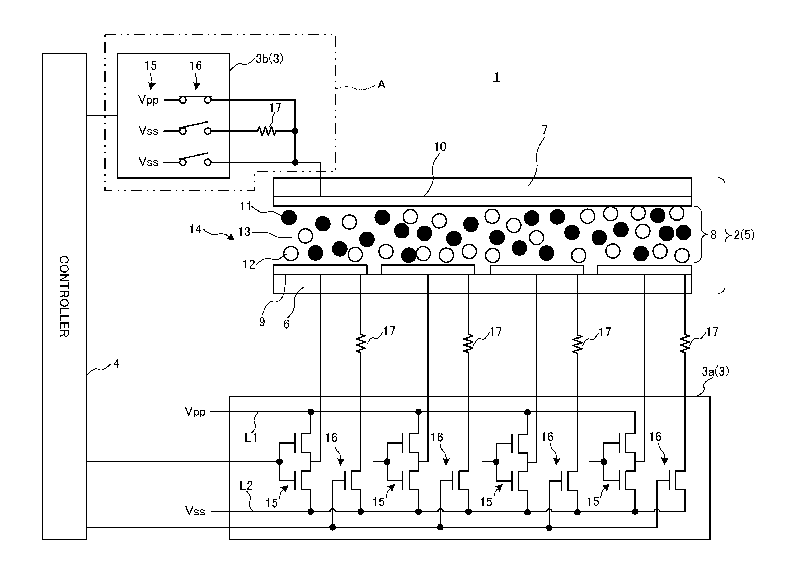
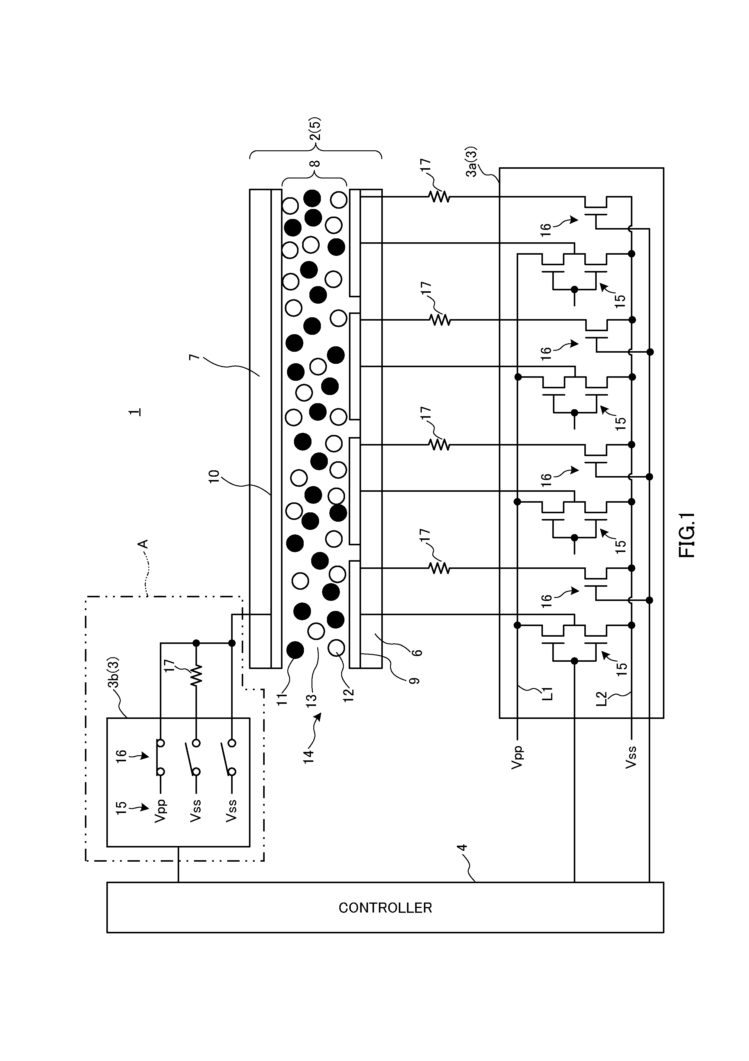
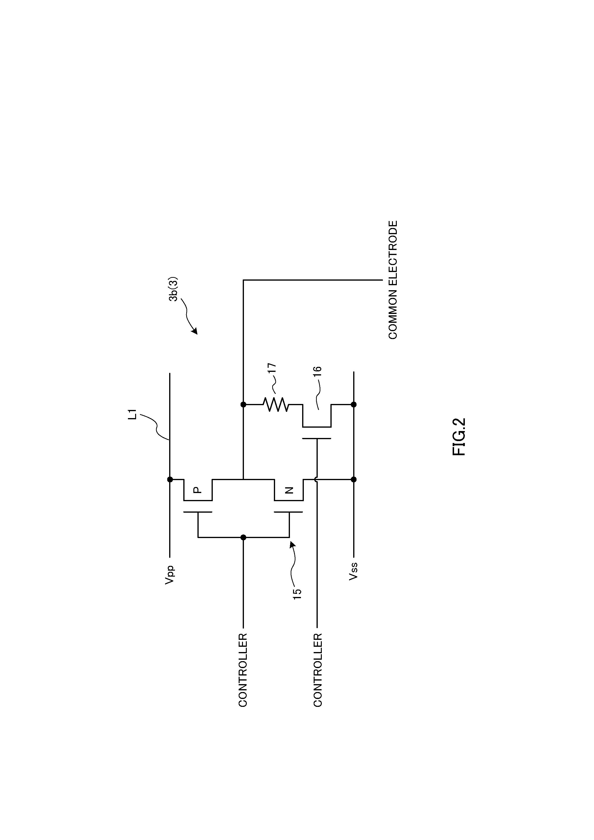
[0032]FIG. 1 is a schematic view of an overall configuration of an electrophoresis display apparatus according to a first embodiment of the present invention. The electrophoresis display apparatus 1 shown in FIG. 1 is provided with a display section 2, a drive circuit (3a, 3b) that drives the display section 2 and a controller 4 that controls operation of the entire apparatus. The drive circuit 3 and the controller 4 constitute drive control means.
[0033]The display section 2 constitutes pixels 5. The display section 2 is provided with an element substrate 6 and an opposite substrate 7 arranged opposite to each other via a spacer (not shown), and an electrophoresis element 8 sealed in between the substrates 6 and 7. The following description will be given assuming that an image is displayed on the opposite substrate 7 side.
[0034]The element substrate 6 is a substrate made, for example, of glass or plastic. The element substrate 6 need not particularly have high optical transparency, ...
example 1
[0051]Next, an example of the electrophoresis display apparatus 1 to which the present invention is applied will be described. FIG. 5 and FIG. 6 are diagrams illustrating a white reflection factor, black reflection factor and contrast result after a write voltage is applied. FIG. 5 illustrates a white reflection factor, black reflection factor and contrast, and the presence / absence of coagulation of charged particles caused by repeated screen switching and general decision result when the resistance value of the resistance 17 is changed. FIG. 6 shows a reflection factor and contrast when pixels are driven with a potential difference of 60 V between the electrodes (a standard value with a potential difference of 50 V between the electrodes is shown for comparison), the electrodes are then short-circuited, left open and connected via a resistance.
[0052]In the present example, the electrophoresis display apparatus 1 of 45 mm×52 mm was used, a PET was used for the element substrate 6 an...
second embodiment
[0055]Next, a second embodiment of the present invention will be described. The electrophoresis display apparatus according to the second embodiment of the present invention is different from the electrophoresis display apparatus according to the first embodiment in that it drives and controls a display section (pixels) where pixels are arranged in a matrix form. Therefore, only differences will be particularly described and identical components will be assigned identical reference numerals and overlapping description thereof will be omitted.
[0056]FIG. 7 is an overall block diagram of the electrophoresis display apparatus according to the second embodiment of the present invention. The electrophoresis display apparatus 20 shown in FIG. 7 is provided with a display section 2 in which pixels are arranged in a matrix form, a data line drive circuit 21 that supplies an image signal to the display section 2, a scanning line drive circuit 22 that supplies a scanning signal to the display ...
PUM
| Property | Measurement | Unit |
|---|---|---|
| resistance | aaaaa | aaaaa |
| volume resistivity | aaaaa | aaaaa |
| voltage | aaaaa | aaaaa |
Abstract
Description
Claims
Application Information
 - R&D
- Intellectual Property
- Life Sciences
- Materials
- Tech Scout
- Unparalleled Data Quality
- Higher Quality Content
- 60% Fewer Hallucinations
Browse by: Latest US Patents, China's latest patents, Technical Efficacy Thesaurus, Application Domain, Technology Topic, Popular Technical Reports.
© 2025 PatSnap. All rights reserved.Legal|Privacy policy|Modern Slavery Act Transparency Statement|Sitemap|About US| Contact US: help@patsnap.com


