
Apparatus for lifting maxillary sinus

a technology for lifting and maxillae, which is applied in the field of apparatus for lifting a maxillary sinus, can solve the problems of patient sequelae, the problem of continuous rotation of the lateral blade, so as to avoid the damage to the maxillary sinus mucous membrane, reduce the drag force, and enhance the patient's safety

Inactive Publication Date: 2013-07-04
METAL INDS RES & DEV CENT
View PDF2 Cites 10 Cited by
  • Summary
  • Abstract
  • Description
  • Claims
  • Application Information

AI Technical Summary

Benefits of technology

The apparatus for lifting a maxillary sinus described in this patent can protect the maxillary sinus mucous membrane from damage during bone removal. It uses a cutting blade and an elastic element to stop the blade from rotating when it encounters a drag force. The apparatus also has an osteotome switch component that allows for both rotary cutting and osteotome mode operation. This enhances dentist security and provides a safer and more effective tool for bone removal procedures.

Problems solved by technology

Currently, a clinically excessive shock may cause sequelae of a patient, such as dizziness and cerebral concussion.
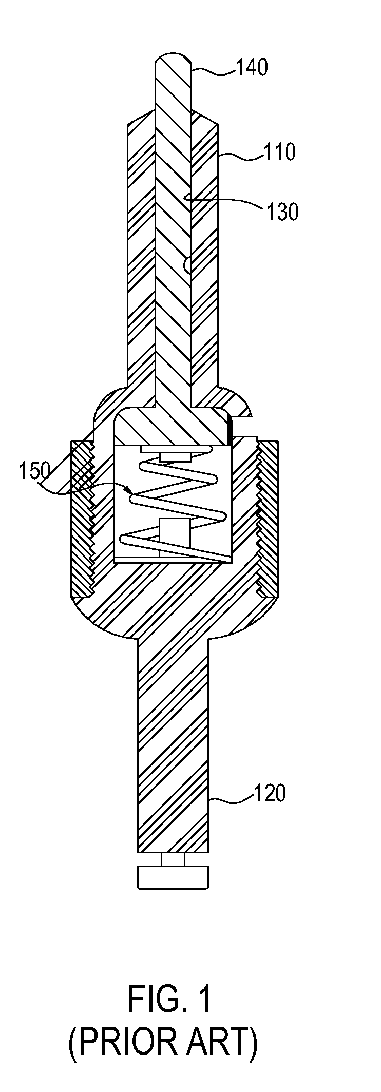
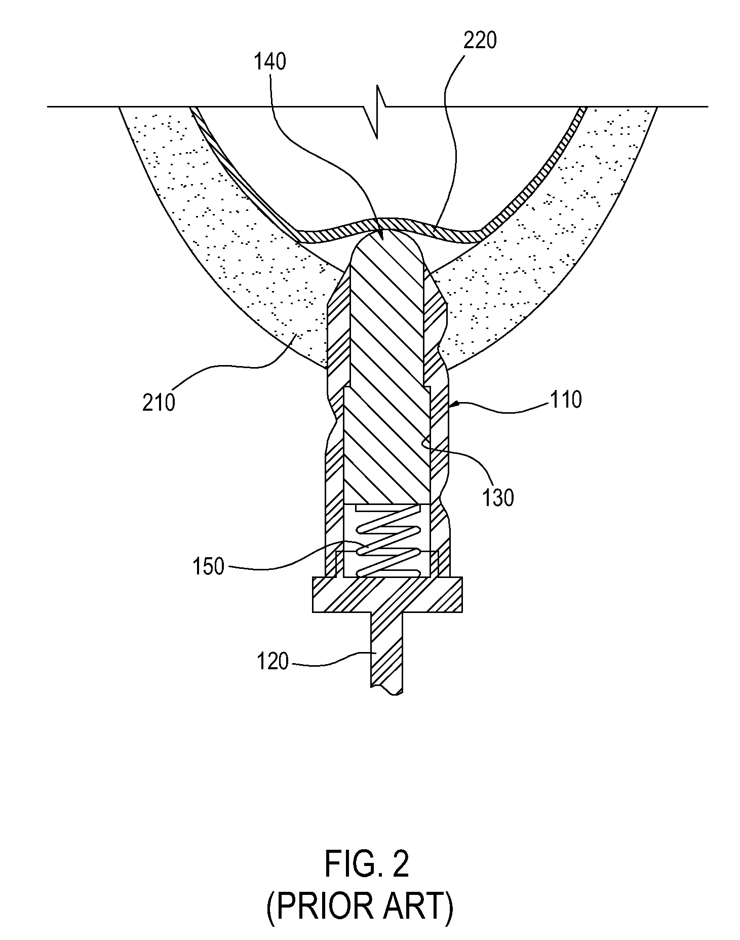
Consequently, the maxillary sinus mucous membrane may be damaged at the instant when the protrusion rod is pushed out.
However, the problem of the damage to the maxillary sinus mucous membrane caused by continuous rotation of the lateral blade remains unsolved.
However, the reamer instrument continuous rotating after damaging the cortical bone 410; despite the flat head design of the cutting blade at the front, the reamer instrument may possibly rub against and hence tear the maxillary sinus mucous membrane 420 due to the rotation.

Method used


Image

  • Apparatus for lifting maxillary sinus
  • Apparatus for lifting maxillary sinus
  • Apparatus for lifting maxillary sinus

Examples


Embodiment Construction

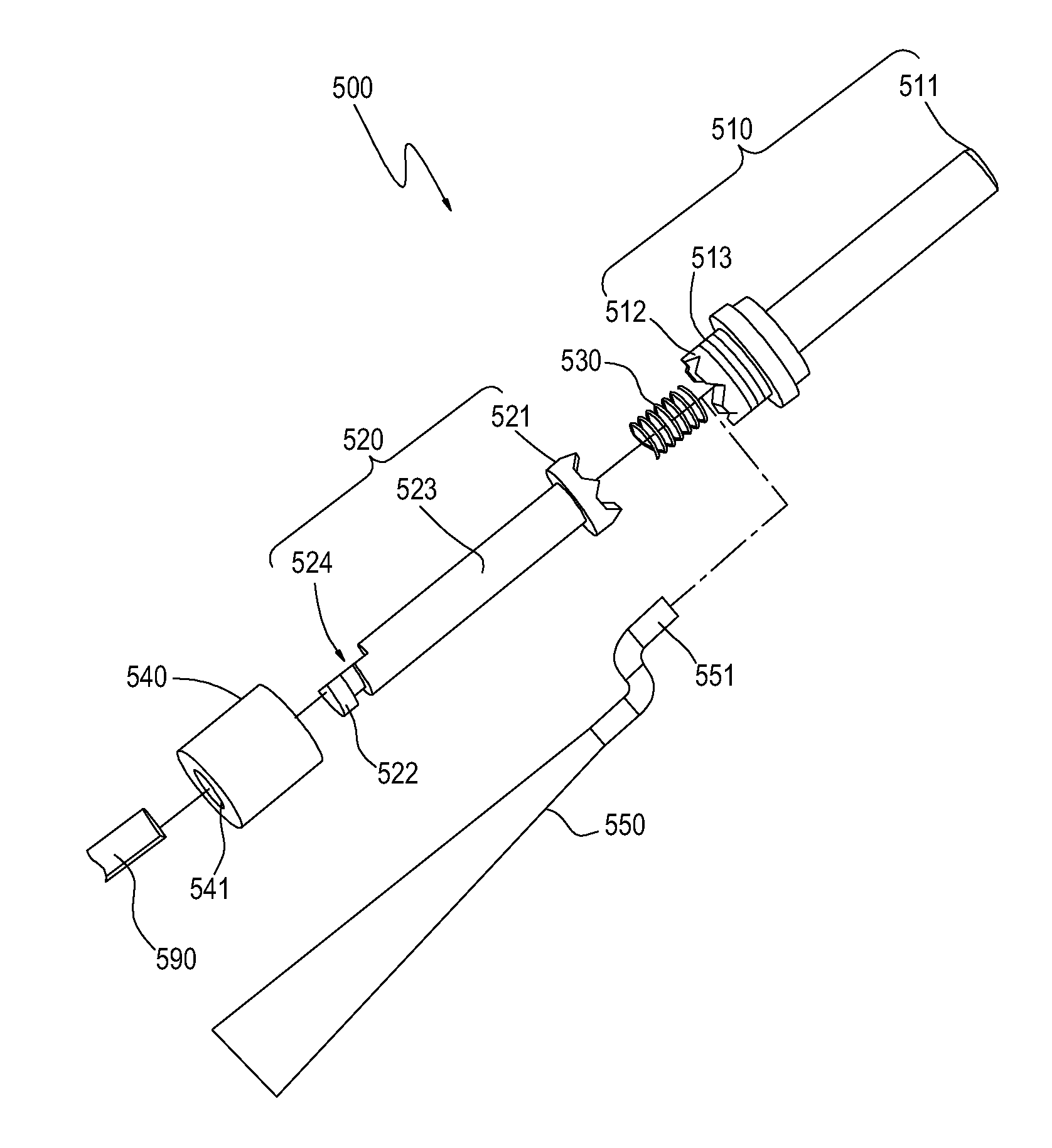
[0024]FIG. 5 is a perspectively exploded view of an apparatus for lifting a maxillary sinus according to an embodiment of the present invention. FIG. 6 (a) and FIG. 6 (b) are assembled sectional views of an apparatus for lifting a maxillary sinus according to an embodiment of the present invention. FIG. 7 is a perspectively view of a pillar of an apparatus for lifting a maxillary sinus according to an embodiment of the present invention. FIG. 8 is a perspectively view of a transmission shaft of an apparatus for lifting a maxillary sinus according to an embodiment of the present invention. Referring to FIG. 5 and FIG. 7, the apparatus 500 for lifting a maxillary sinus includes a pillar 510. The pillar 510 is cylindrical, and one end of the pillar 510 is a top portion. The top portion is a cutting blade 511 that has a function of cutting or damaging a cortical bone. From a side view, a lowest point of the cutting blade 511 is at a rotational axis, and a highest point of the cutting bl...


PUM


Abstract

An apparatus for lifting a maxillary sinus includes: a pillar, having a cutting blade and an engaging base; a transmission shaft, having a transmission base having a shape corresponding to that of the engaging base; an elastic element provided an elastic force between the engaging base and the transmission base; and a seal element, wrapping the engaging base, the elastic element and the transmission base. When the cutting blade encounters a drag force, the transmission base moves toward the engaging base until the transmission base and the engaging base are engaged with each other. When the drag force is decreased, the engaged transmission base and engaging base are separated from each other due to the elastic force of the elastic element.

Description

CROSS-REFERENCE TO RELATED APPLICATION[0001]This application claims the benefit of Taiwan Patent Application No. 100149129, filed on Dec. 28, 2011, which is hereby incorporated by reference for all purposes as if fully set forth herein.BACKGROUND OF THE INVENTION[0002]1. Field of Invention[0003]The present invention relates to an apparatus for lifting a maxillary sinus, and in particular, to an apparatus for lifting a maxillary sinus capable of immediately stopping rotary cutting of a cutting blade when penetrating a cortical bone.[0004]2. Related Art[0005]In a dental implant operation, an implant can be tightly implanted into a gingival bone only after a bone cutting operation is performed on an alveolar bone and a round hole is drilled by a drill bit.[0006]However, in current dental implant operations, when the height of the maxilla of a patient is insufficient, a maxillary sinus mucous membrane of the patient needs to be lifted, a sufficient amount of a bone needs to be transplan...

Claims


Application Information

Patent Timeline
Patent Type & Authority Applications(United States)
IPC IPC(8): A61C8/00
CPCA61C8/0092
Inventor HUANG, CHING-CHIEHLUO, KAI- SHILIU, NAN-YUCHENG, E-HSUNGKUO, SHIEN-NAN
Owner METAL INDS RES & DEV CENT
Learn More