
Free casting method, free casting apparatus, and casting

Active Publication Date: 2013-07-04
TOYOTA CENT RES & DEV LAB INC +1
View PDF0 Cites 15 Cited by
  • Summary
  • Abstract
  • Description
  • Claims
  • Application Information

AI Technical Summary

Benefits of technology

The present invention provides a method for casting alloys without using conventional casting molds, which can prevent casting defects. This method can be used for alloys that are likely to solidification cracking or shrinkage porosity. It also allows for obtaining complicated shaped castings made of these alloys. The method prevents solidification cracking by not cooling the molten metal in the casting mold. The technical effects of this invention are a wider selection of alloys for obtaining castings and prevention of casting defects.

Problems solved by technology

Therefore, the casting methods conventionally employed often led to a variety of problems caused by using the casting moulds.
The problems are, for example, casting defects (solidification cracking, shrinkage porosity, gas blow holes, etc.), ununiformity of solidified structure, deterioration of material yield, environmental burden, or the like.

Method used


Image

  • Free casting method, free casting apparatus, and casting
  • Free casting method, free casting apparatus, and casting
  • Free casting method, free casting apparatus, and casting

Examples


example 1

[0071]The present invention is described in further detail referring to examples.

[0072]

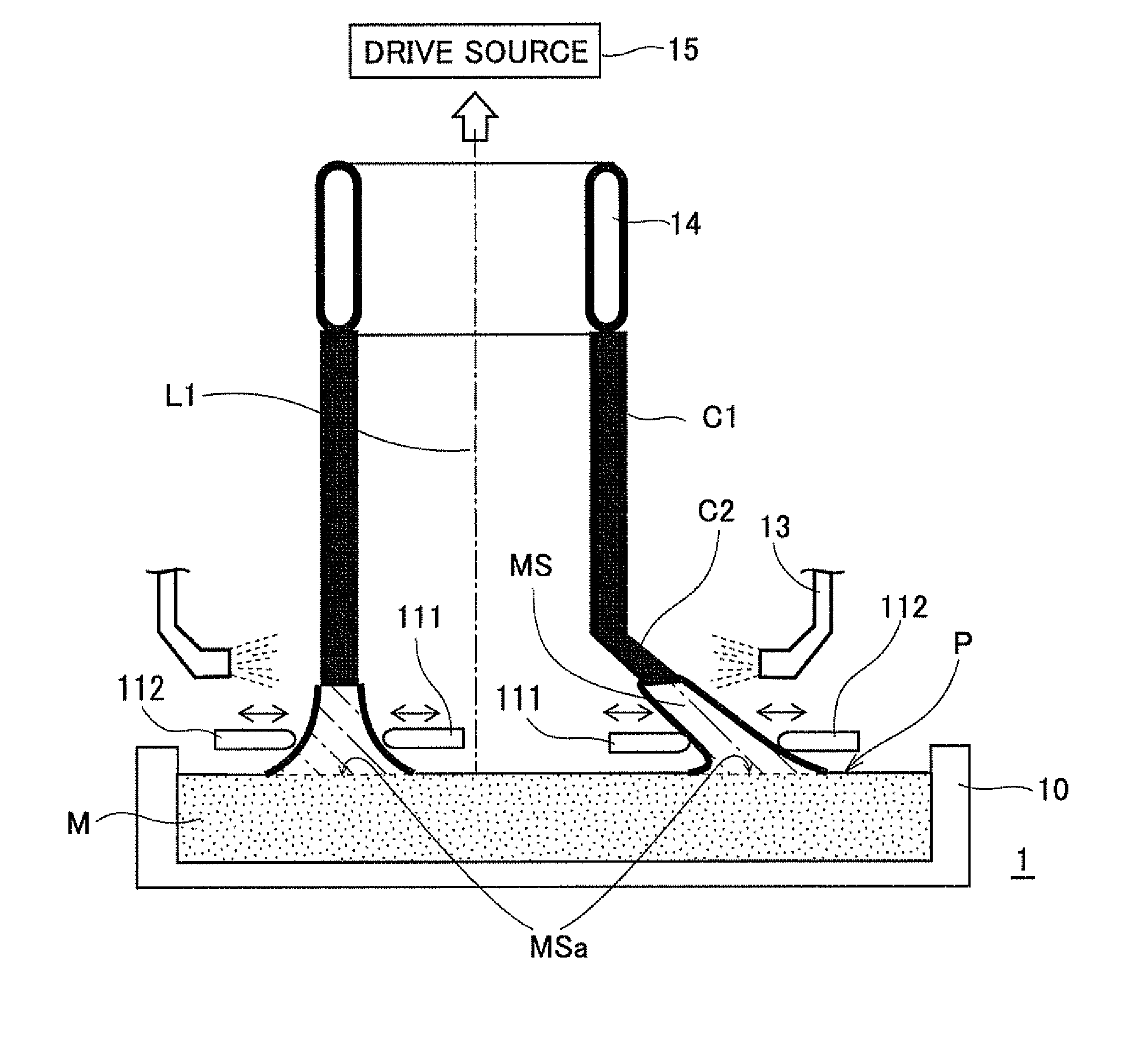
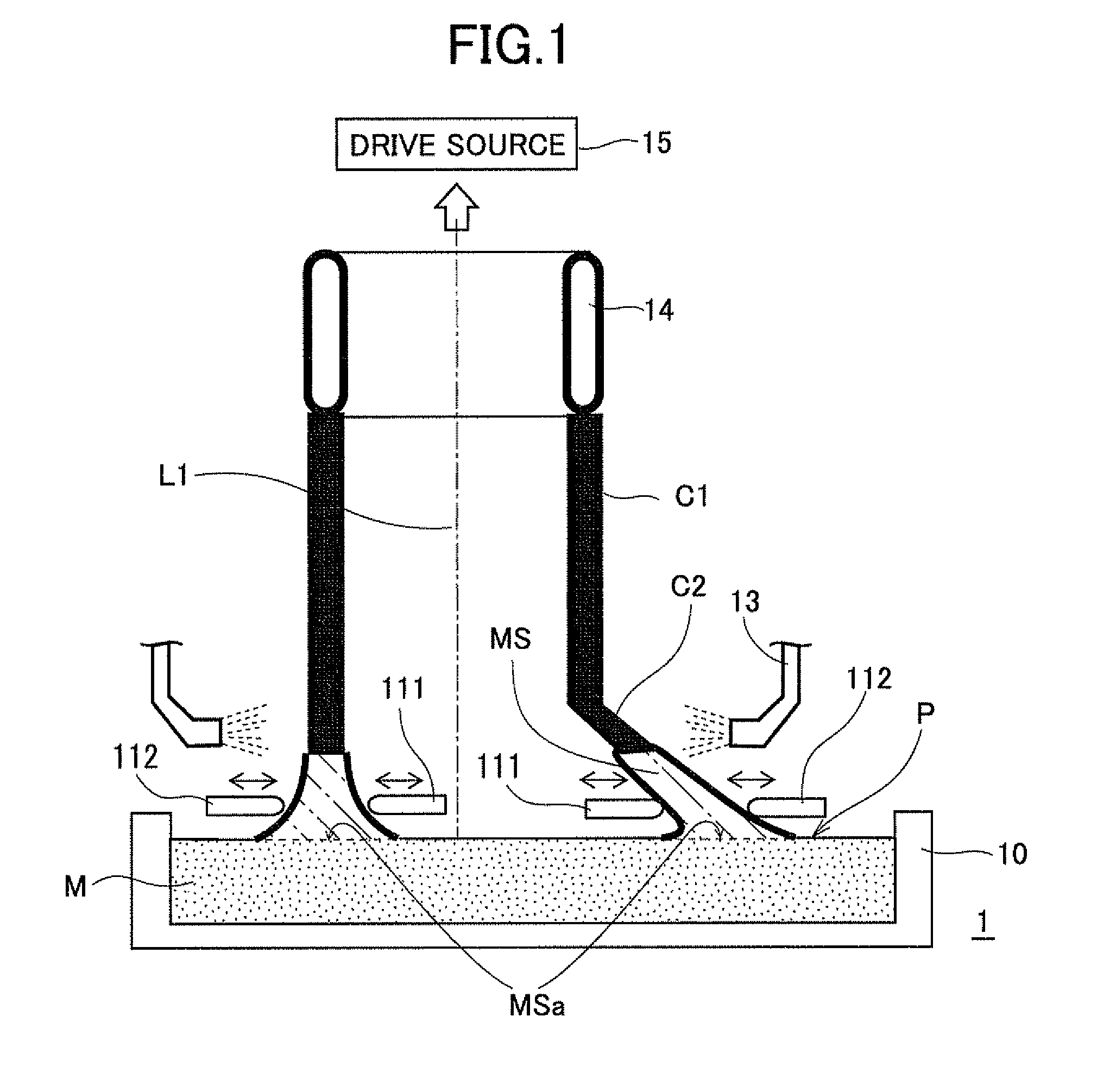
[0073](1) FIG. 1 is a conceptual view of a free casting apparatus 1. FIG. 2 is an enlarged view of a part of the free casting apparatus shown in FIG. 1. The free casting apparatus 1 has a crucible 10 in which molten metal M is contained, and an inner shape providing member 111 and an outer shape providing member 112 provided shortly above a surface level of the molten metal M in the crucible 10 (which are collectively called “shape providing members 11”), a plurality of cooling nozzles 13 provided in an upward direction of the shape providing members 11 from which a coolant G is blown out approximately annularly, a starter 14 (inducing body) made of metal and having an annular shape in section, and a drive source 15 which lifts up the starter 14.

[0074]The drive source 15 can control a lift-up speed (ascending speed) of the starter 14 and a lift-up direction (moving direction) of the starter 14. Th...

example 2

Free Casting Method

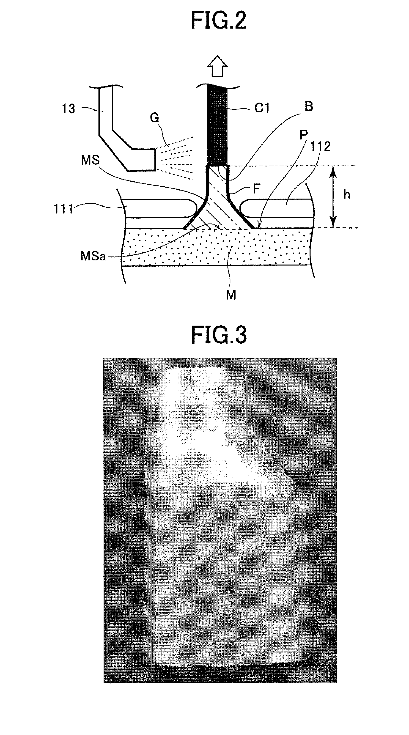
[0085]FIGS. 5 and 6 are images of another casting obtained by the free casting apparatus 1. To obtain a casting C3 shown in FIG. 5, the horizontal (rightward and leftward) moving speed of the starter 14 and the ascending speed of the starter 14 were set to 1:1, and the retained molten metal MS was guided along a zig-zag passage (set passage) tilted from the vertical direction by about 45 degrees and then formed. The casting C3 also had directional solidified structure. The casting C3 showed no casting defect such as shrinkage porosity or solidification cracking, and had a smooth and fine casting surface.

[0086]To obtain a casting C4 shown in FIG. 6, the traveling passage of the starter 14 (guiding passage of the retained molten metal MS) having the zig-zag shape is changed to a passage having a spiral shape (set passage), and the retained molten metal MS is then formed. More specifically, the starter 14 was brought into contact with the molten metal M in the lead-o...


PUM

PropertyMeasurementUnit
Structureaaaaaaaaaa
Shapeaaaaaaaaaa
Surface tensionaaaaaaaaaa

Abstract

A free casting method according to the present invention includes, a lead-out step for leading out molten metal from a lead-out area provided in a source of supply, e.g. a surface level of the molten metal, to retain the molten metal temporarily by surface films generated on an outer surface, and a forming step for obtaining a formed body by solidifying retained molten metal led out along a set passage depending on a desired casting shape, wherein the retained molten metal is solidified after being formed into the desired casting shape by applying an external force thereto at positions between an unrestrained root portion of the retained molten metal in vicinity of the surface level of the molten metal and a solidification interface defined as a boundary between the retained molten metal and the formed body in the forming step.

Description

TECHNICAL FIELD[0001]The present invention relates to a breakthrough casting method (hereinafter, called “free casting method”) which is capable of obtaining a casting without using a casting mould which was conventionally believed to be indispensable for casting, and a free casting apparatus suitably used for the method, and a casting obtained by the method and the apparatus.BACKGROUND ART[0002]Metal products formed in complicated shapes are often produced by casting. Casting is a production process in which metal having fluidity (molten metal) is solidified in a desired shape to obtain a target casting. It is technical common knowledge long believed that a casting mould having a cavity suitable for a desired shape of a target casting is an indispensable device for casting. Therefore, the casting methods conventionally employed often led to a variety of problems caused by using the casting moulds. The problems are, for example, casting defects (solidification cracking, shrinkage po...

Claims


Application Information

Patent Timeline
IPC IPC(8): B22D11/01
CPCB22D11/01B22D11/05B22D11/145B22D27/045B22D11/041
Inventor YAOKAWA, JUNIWATA, YASUSHISUGIYAMA, YOSHIOIWAHORI, HIROAKIAMANO, NORIHIROUENO, NORIYUKIKOBAYASHI, TAKEHITO
Owner TOYOTA CENT RES & DEV LAB INC
Learn More