
Drive circuit, drive method, and display device

a drive circuit and drive method technology, applied in the direction of electric digital data processing, instruments, computing, etc., can solve the problem of reducing the degradation of image quality, and achieve the effect of reducing image degradation and responsiveness

Inactive Publication Date: 2013-06-27
SHARP KK
View PDF6 Cites 9 Cited by
  • Summary
  • Abstract
  • Description
  • Claims
  • Application Information

AI Technical Summary

Benefits of technology

The present invention improves the response time and reduces image degradation in a display device with a backlight.

Problems solved by technology

This reduces the degradation of the image quality.

Method used


Image

  • Drive circuit, drive method, and display device
  • Drive circuit, drive method, and display device
  • Drive circuit, drive method, and display device

Examples


first embodiment

[0033]The first embodiment of the present invention will be described with reference to the drawings.

1. Configuration of the Display Device

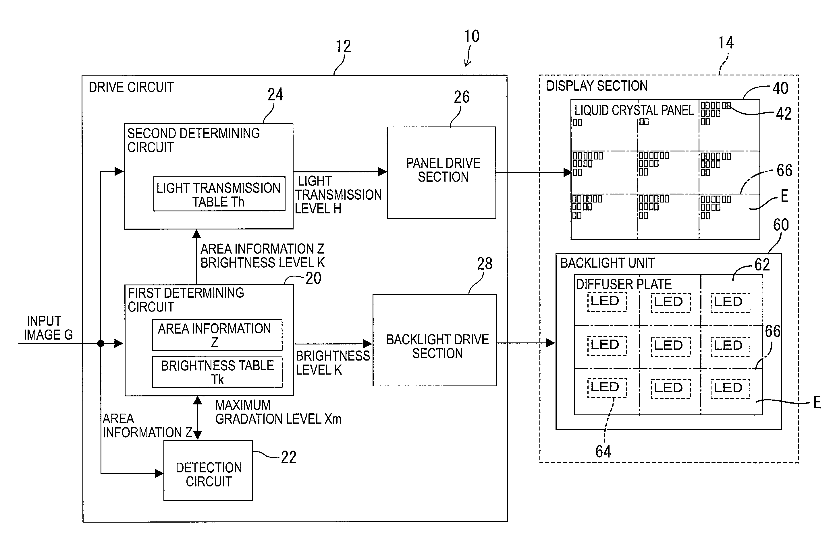
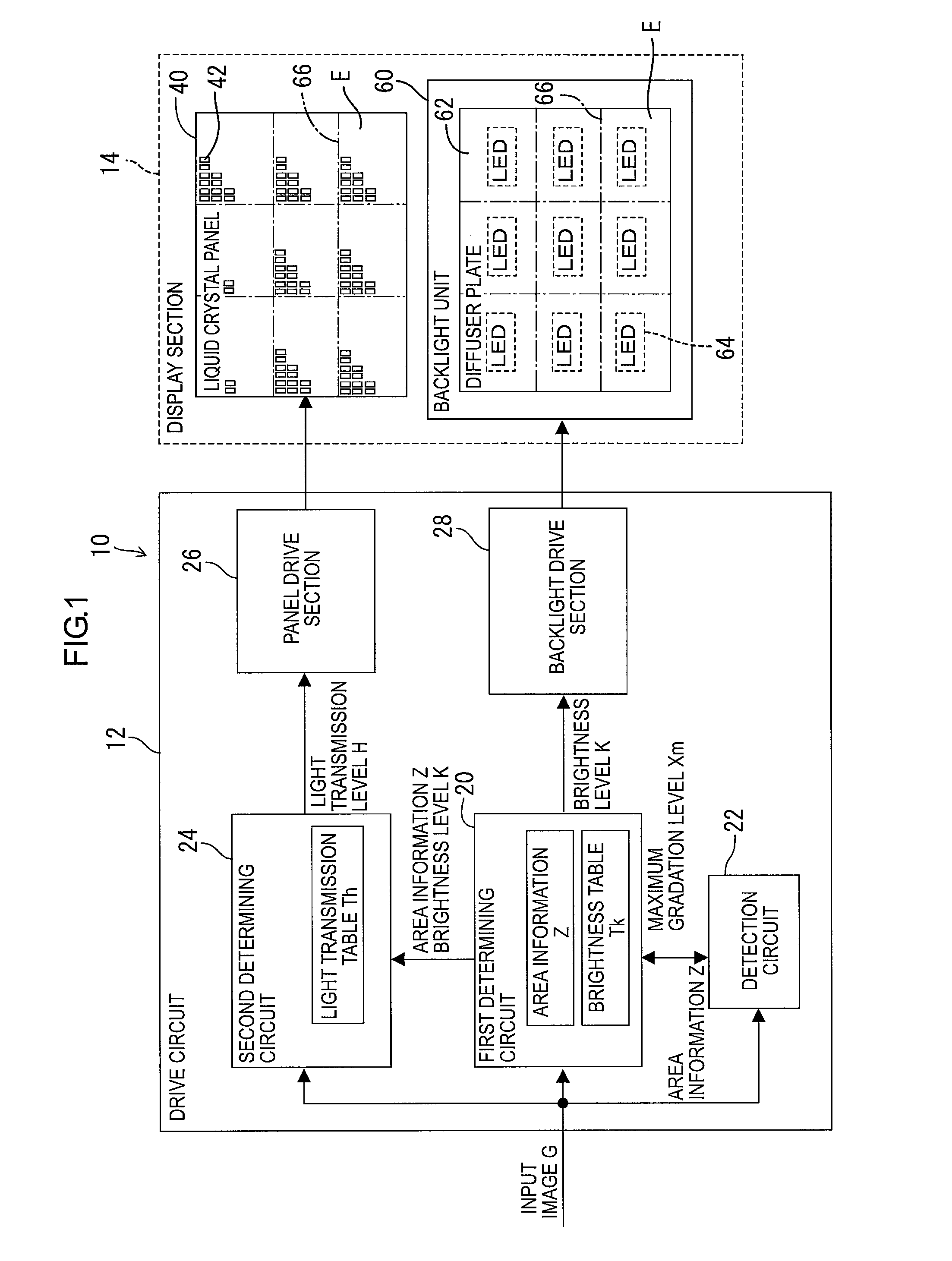
[0034]As illustrated in FIG. 1, a display device 10 includes a drive circuit 12 and a display section 14. The display section 14 includes a liquid crystal panel 40 (an example of a liquid crystal display element) and a backlight unit 60.

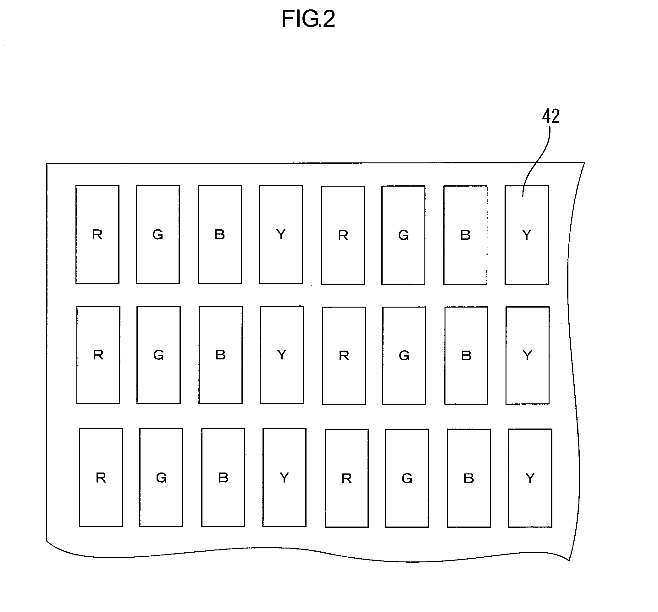
[0035]The liquid crystal panel 40 includes a plurality of pixels 42. FIG. 2 is a magnified view of apart of the liquid crystal panel 40. The liquid crystal panel 40 includes four kinds of pixels 42 (an example of display element). The pixels 42 include a pixel R through which a red light passes, a pixel G through which a green light passes, a pixel B through which a blue light passes, and a pixel Y through which a yellow light passes. The pixel R, the pixel G, the pixel B, and the pixel Y are aligned in a row in this order and such a row is aligned in columns.

[0036]FIG. 3 illustrates an equivalent circuit of the ...


PUM


Abstract

A drive circuit is configured to drive a display panel including pixels and a backlight including LEDs. The display panel includes a critical light transmission level that is a minimum level for causing each pixel to respond in a predetermined time upon an input of an image. The drive circuit includes first and second circuits. The first circuit is configured to divide the image into areas and determine brightness levels of the LEDs for the areas based on the image. The second circuit is configured to determine a light transmission level based on the image and the brightness levels such that the level is higher than the critical level.

Description

TECHNICAL FIELD [0001]The present invention relates to a drive circuit, a drive method, and a display device, in particular to a technology for driving a display device including a backlight while controlling brightness of the backlight and light transmission of a display panel.BACKGROUND ART [0002]In recent years, high-performance liquid crystal display devices such as a large screen television have been widely used. The liquid crystal display device has advantages such as light weight and small heat radiation compared to a conventional monitor using cathode ray tubes. However, a liquid crystal display device including a backlight has problems in power consumption and responsiveness. The liquid crystal display device is developed to solve the problems.[0003]Patent Document 1 discloses an area-active drive as a technology that reduces the power consumption of the liquid crystal display device including a backlight. According to this technology, a display is divided into a plurality ...

Claims


Application Information

Patent Timeline
Patent Type & Authority Applications(United States)
IPC IPC(8): G09G5/10
CPCG09G3/3426G09G5/10G09G2320/0646
Inventor YAMAKAWA, RYO
Owner SHARP KK
Learn More