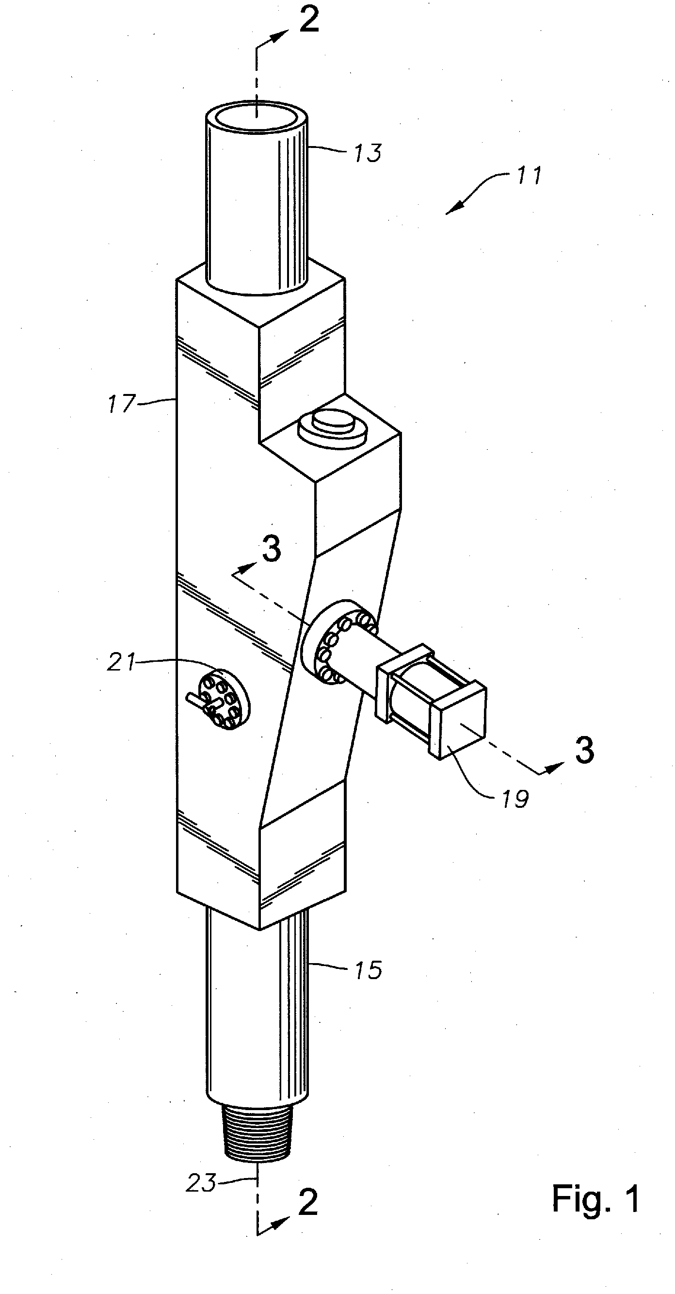
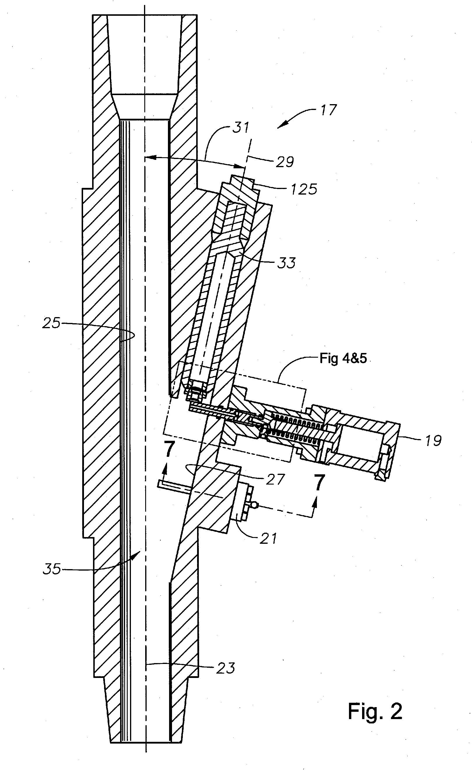
Modular dart launcher with status indicator

a technology of status indicator and launcher, which is applied in the direction of fluid removal, sealing/packing, and wellbore/well accessories, etc., can solve the problems of preventing successful release of dart or drop ball, clogging, and difficult access to the launcher, so as to achieve the effect of easy launch of ball, dart or plug, and minimal human intervention

Inactive Publication Date: 2013-06-27
VETCO GRAY
View PDF9 Cites 6 Cited by
  • Summary
  • Abstract
  • Description
  • Claims
  • Application Information

AI Technical Summary

Benefits of technology

[0012]An advantage of a preferred embodiment is that it provides a dart launcher that may be used in high fluid pressures situations. In addition, the disclosed embodiments provide an apparatus and method to easily launch a ball, dart, or plug with minimal human intervention. Still further, the disclosed embodiments provide a modular apparatus that allows for variation in the size of the ball, dart, or plug launched. Sill further, the disclosed embodiment provides a visual indicator for an operator to confirm the successful launch of the ball, dart, or plug that does not rely on complicated electronics systems that may be prone to failure in harsh operating environments.

Problems solved by technology

The height can make the launcher very difficult to access and operate.
The dart or ball may become stuck or snagged at the valve openings, preventing successful release of the dart or drop ball.
These passages restrict fluid flow through the running string and may become clogged.
Clogging of these passages will, in turn, require stoppage of drilling operations in order to remove and reset the launcher for operation.
Even when not blocked, these passages may restrict the flow of fluid downhole, causing further complications in drilling operations.
These devices rely on complex landing and sliding sleeve devices, to bypass the fluids around the landed balls and darts, again restricting fluid flow through the string.
These devices also do not provide an indication that the proper dart or plug has been launched following landing of the ball.
However, in some wells, particularly in deep subsea wells, the distances between the operating platform and the landing location are large enough that it may take over an hour for the dart to land at the seat.
In the event that the ball, dart, or plug becomes hung up or snagged in the launcher and does not release into the tubing string, the well may be significantly damaged, necessitating expensive and time consuming repair operations.
Some launchers include an electrical system for indicating that the dart, ball, or plug has released, however these systems require complex components that are prone to failure and difficult to adapt to changing types and sizes of balls, darts, and plugs.

Method used


Image

  • Modular dart launcher with status indicator
  • Modular dart launcher with status indicator
  • Modular dart launcher with status indicator

Examples


Embodiment Construction

[0028]The present invention will now be described more fully hereinafter with reference to the accompanying drawings which illustrate embodiments of the invention. This invention may, however, be embodied in many different forms and should not be construed as limited to the illustrated embodiments set forth herein. Rather, these embodiments are provided so that this disclosure will be thorough and complete, and will fully convey the scope of the invention to those skilled in the art. Like numbers refer to like elements throughout, and the prime notation, if used, indicates similar elements in alternative embodiments or positions.

[0029]In the following discussion, numerous specific details are set forth to provide a thorough understanding of the present invention. However, it will be obvious to those skilled in the art that the present invention may be practiced without such specific details. Additionally, for the most part, details concerning drilling rig operation, well tool manufa...


PUM


Abstract

A dart launcher launches a dart by placing the dart within a launcher bore formed within a launcher body. The launcher body also defines a central bore coupled inline with a tubing string and in fluid communication with the launcher bore. The launcher bore is formed at an angle to the central bore. A release assembly is coupled to the launcher body and includes a release rod protruding into the launcher bore to selectively release the dart. A visual indicator assembly is coupled to the launcher body downstream from the release assembly and includes a flapper protruding into the launcher bore. The release assembly is actuated by the dart rotating the flapper to rotate an arm from a non-released position to a released position.

Description

BACKGROUND OF THE INVENTION[0001]1. Field of the Invention[0002]This invention relates in general to drop balls, plugs, or darts used to operate well tool functions and, in particular, to a drop ball, plug, or dart launcher with a status indicator.[0003]2. Brief Description of Related Art[0004]Standard dart or ball launchers have a member that defines a central bore that may be coupled inline with a drill or tubing string. The launchers also include an angular bore that intersects the central bore at a shallow angle between the angular bore and the central bore. A dart or ball is dropped into the angular bore, and after opening a series of valves, the ball or dart is introduced into the central bore for further movement of the dart or ball down the borehole. There, the dart or ball will land at a predetermined location to block the borehole and allow hydraulic tool operations. In order to minimize the potential that the ball will snag or hang up as it moves from the angular bore to ...

Claims


Application Information

Patent Timeline
Patent Type & Authority Applications(United States)
IPC IPC(8): E21B33/13
CPCE21B23/10E21B33/05
Inventor YATES, CHAD ERICHEDGE, SHRIPADNARAYAN, DINESH
Owner VETCO GRAY
Why Eureka
Try Eureka