Eureka AIR delivers breakthrough ideas for toughest innovation challenges, trusted by R&D personnel around the world.

Apparatus and method for forming pilot holes in bone and delivering fasteners therein for retaining an implant

a pilot hole and bone technology, applied in the field of orthopedic medicine and surgery, can solve the problems of rotator cuff damage, a potentially serious medical condition, complex mechanical properties of the rotator cuff muscles,

Active Publication Date: 2013-06-20
ROTATION MEDICAL
View PDF5 Cites 63 Cited by
  • Summary
  • Abstract
  • Description
  • Claims
  • Application Information

AI Technical Summary

Benefits of technology

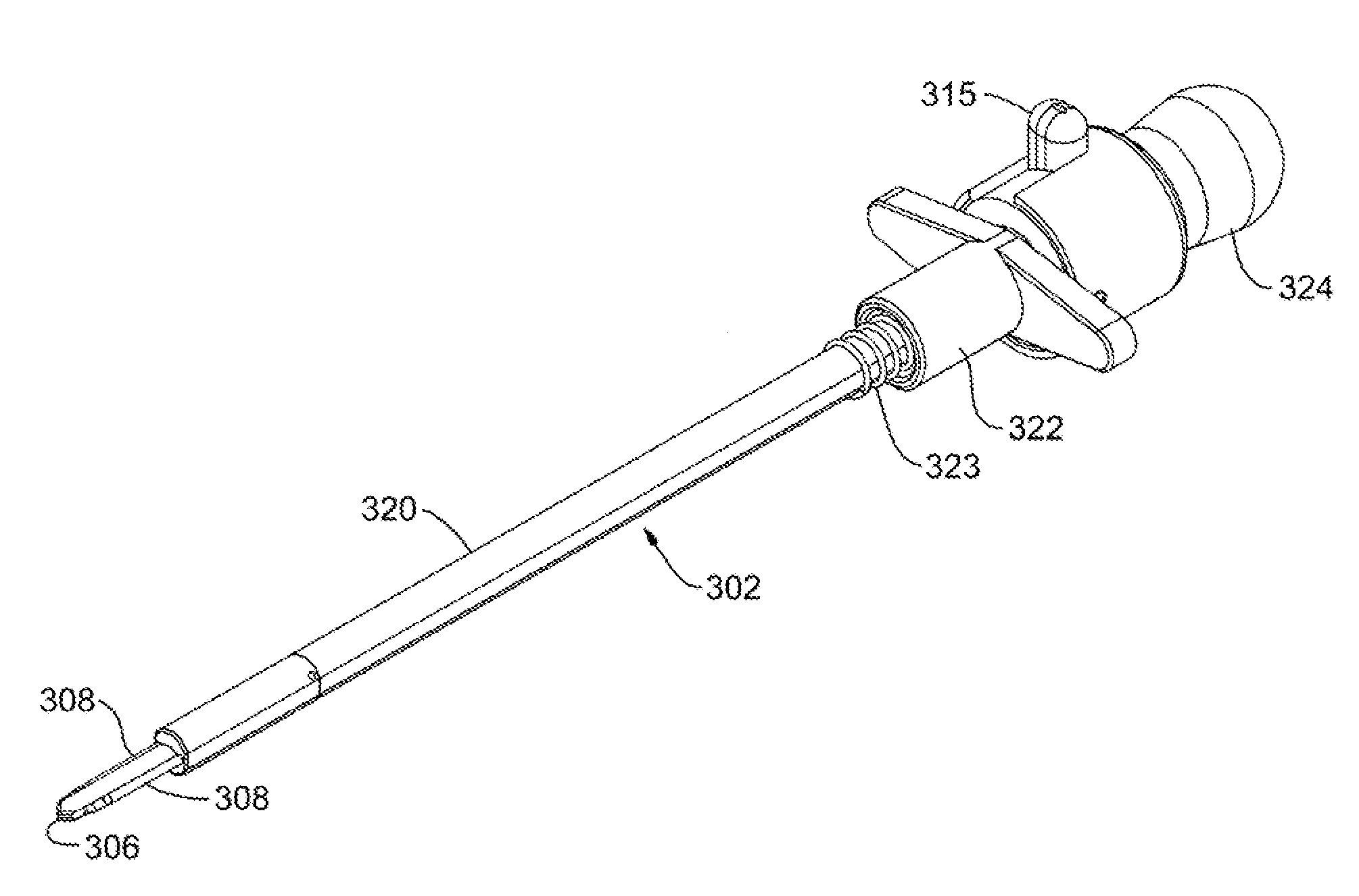
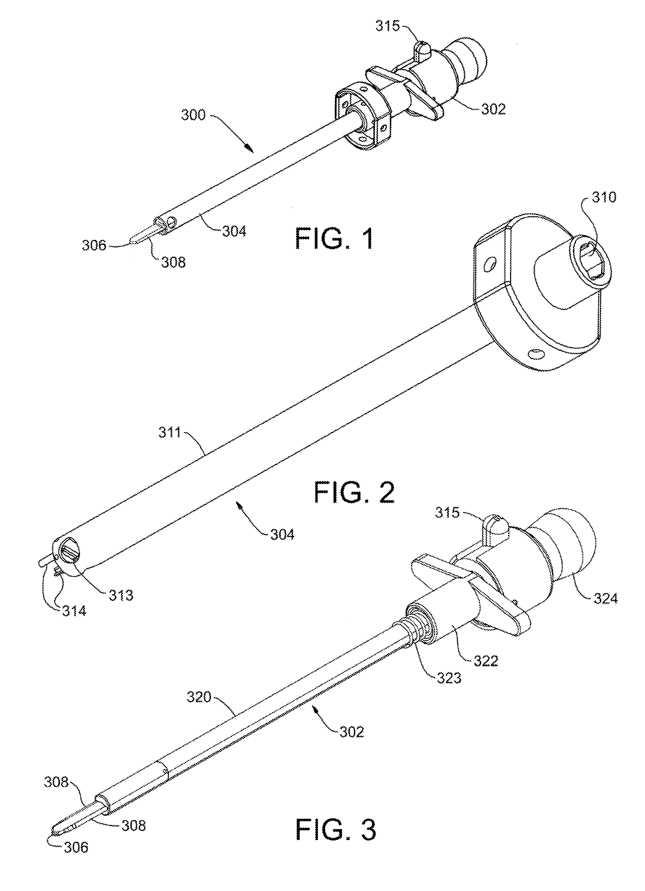
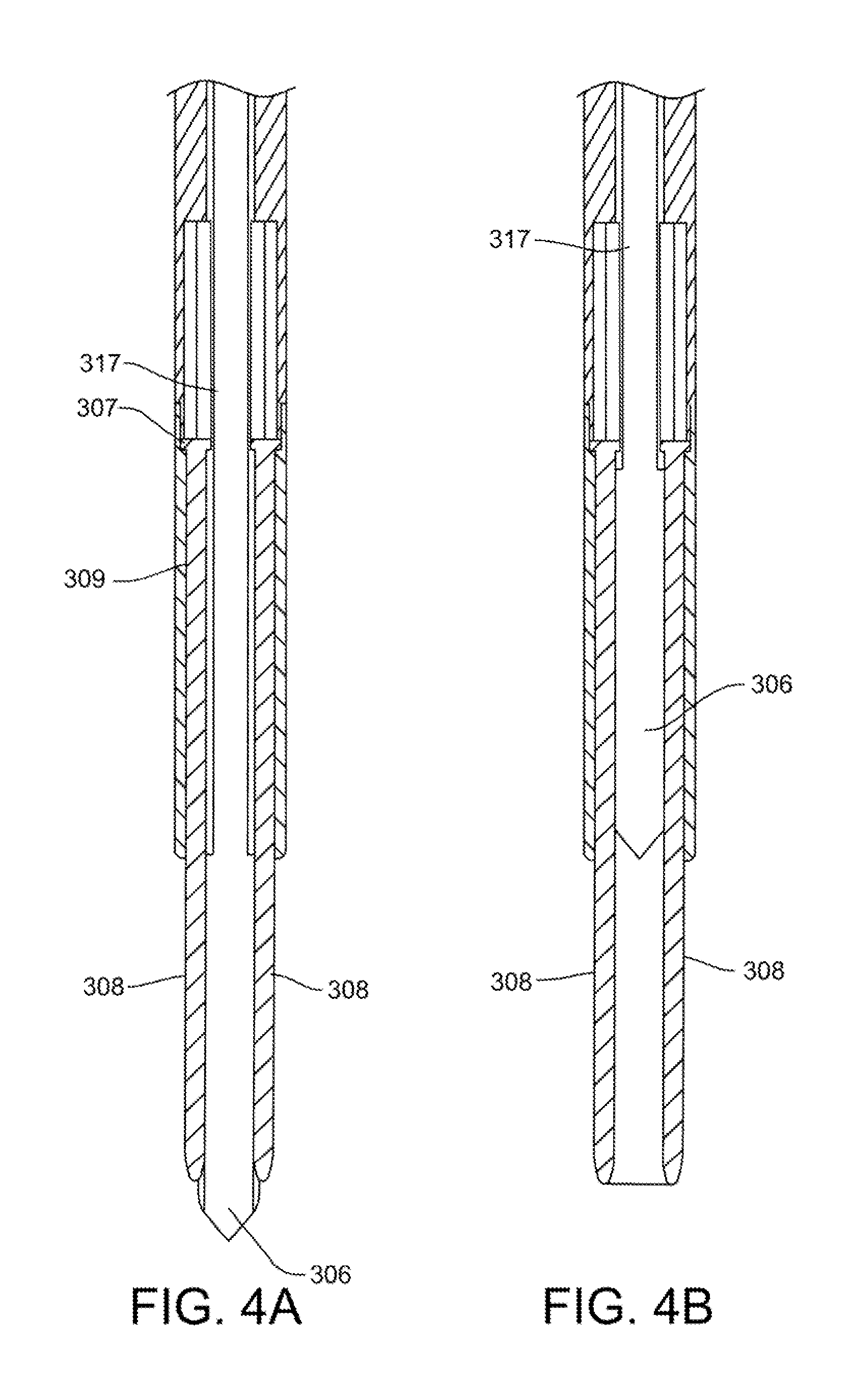
The present patent is about an arthroscopic apparatus and method to create pilot holes in bone and keep an instrument in position to deliver a fastener to those holes. This can be useful for procedures where a sheet-like material or implant needs to be fixed to bone, such as in a rotator cuff repair. The apparatus includes a pilot hole forming trocar assembly with a position retention sleeve and atrocar, which can form pilot holes and keep an instrument in place. The staple delivery device can then be inserted to deliver a staple to the bone. The technical effects of this patent are improved accuracy and efficiency in creating pilot holes and delivering a fastener to bone, which can lead to better outcomes for patients and surgeons.

Problems solved by technology

The mechanics of the rotator cuff muscles are complex.
With its complexity, range of motion and extensive use, a common soft tissue injury is damage to the rotator cuff or rotator cuff tendons.
Damage to the rotator cuff is a potentially serious medical condition that may occur during hyperextension, from an acute traumatic tear or from overuse of the joint.
A tear at the insertion site of the tendon with the humerus, may result in the detachment of the tendon from the bone.
Additionally, the strain or tear can occur within the tendon itself.
In many instances, the shoulder does not heal and the partial thickness tear can be the source of chronic pain and stiffness.
Further, the pain and stiffness may cause restricted use of the limb which tends to result in further degeneration or atrophy in the shoulder.
Surgical intervention may be required for a partial thickness tear of less than 50%, however, current treatment interventions do not include repair of the tendon, and rather the surgical procedure is directed to arthroscopic removal of bone to relieve points of impingement or create a larger tunnel between the tendon and bone that is believed to be causing tendon damage.
This may result in less use of the arm and shoulder which causes further degeneration of the tendon and may lead to more extensive damage.
This procedure requires extensive rehabilitation, has relatively high failure rates and subjects the patient who first presented and was treated with a partial thickness tear less than 50% to a second surgical procedure.
As described above, adequate treatments do not currently exist for repairing a partial thickness tear of less than 50% in the supraspinatus tendon.
Current procedures attempt to alleviate impingement or make room for movement of the tendon to prevent further damage and relieve discomfort but do not repair or strengthen the tendon.
Use of the still damaged tendon can lead to further damage or injury.
Prior damage may result in degeneration that requires a second more drastic procedure to repair the tendon.
Further, if the prior procedure was only partially successful in relieving pain and discomfort, a response may be to use the shoulder less which leads to degeneration and increased likelihood of further injury along with the need for more drastic surgery.

Method used


Image

  • Apparatus and method for forming pilot holes in bone and delivering fasteners therein for retaining an implant
  • Apparatus and method for forming pilot holes in bone and delivering fasteners therein for retaining an implant
  • Apparatus and method for forming pilot holes in bone and delivering fasteners therein for retaining an implant

Examples


Embodiment Construction

[0035]The following detailed description should be read with reference to the drawings in which similar elements in different drawings are numbered the same. The drawings, which are not necessarily to scale, depict illustrative embodiments and are not intended to limit the scope of the invention.

[0036]Apparatus and methods as described in this disclosure can be used to position and deploy fasteners or staples to attach tissue and implants to bone. In at least some applications, the staple is generally flexible and include a pair of arms connected by a bridge with the arms having trunk portions thereon. Staples can include those disclosed in co-pending applications U.S. Provisional Application No. 61 / 577,626 filed on Dec. 19, 2011, Attorney Docket No. 10322-712.100 entitled, “FASTENERS AND FASTENER DELIVERY DEVICES FOR AFFIXING SHEET-LIKE MATERIALS TO BONE OR TISSUE”; U.S. Provisional Application No. 61 / 577,632 filed on Dec. 19, 2011, Attorney Docket No. 10322-713.100 entitled, “FAST...


PUM


Abstract

Apparatus and methods for forming pilot holes in bone and deploying a staple therein for fixing a sheet-like implant to the bone. A pilot hole forming trocar assembly including a trocar and a position retention sleeve can be included. The trocar can be releasably coupled to the position retention sleeve and slide in keyed arrangement within the sleeve when uncoupled. The trocar can include a distal portion having a retractable blade and a pair of pilot hole forming spikes extending distally from the trocar shaft. Once the pilot holes are formed, the position retention sleeve maintains the position relative to the pilot holes while the trocar is removed and a staple delivery device can be inserted in the lumen of the position retention sleeve to deploy a staple in the pilot holes.

Description

CROSS REFERENCE TO RELATED APPLICATIONS[0001]This application claims priority to U.S. Provisional Application No. 61 / 577,621 filed on Dec. 19, 2011, the disclosure of which is incorporated by reference herein.[0002]The present disclosure is also related to the following commonly assigned co-pending applications the disclosures of which are incorporated herein by reference: U.S. Provisional Application No. 61 / 577,626 filed on Dec. 19, 2011, Attorney Docket No. 10322-712.100 entitled, “FASTENERS AND FASTENER DELIVERY DEVICES FOR AFFIXING SHEET-LIKE MATERIALS TO BONE OR TISSUE”; U.S. Provisional Application No. 61 / 577,632 filed on Dec. 19, 2011, Attorney Docket No. 10322-713.100 entitled, “FASTENERS AND FASTENER DELIVERY DEVICES FOR AFFIXING SHEET-LIKE MATERIALS TO BONE OR TISSUE” and U.S. Provisional Application No. 61 / 577,635 filed on Dec. 19, 2011, Attorney Docket No. 10322-714.100 entitled, “FASTENERS AND FASTENER DELIVERY DEVICES FOR AFFIXING SHEET-LIKE MATERIALS TO BONE OR TISSUE...

Claims


Application Information

Patent Timeline
Patent Type & Authority Applications(United States)
IPC IPC(8): A61B17/34
CPCA61F2/0811A61B17/0642A61B17/1604A61B17/0682A61B17/3472A61B2017/3454A61B2017/3488A61B17/3468A61B17/068A61B17/56A61B17/88A61B17/8872A61B2017/564
Inventor EUTENEUER, CHARLES L.WESTLING, THOMAS A.ZENZ-OLSON, NATHANIEL Z.WITZMANN, MICHAEL
Owner ROTATION MEDICAL
Why Eureka
Eureka Blog
Learn More