
System for magnetic field distortion compensation and method of making same

a magnetic field and compensation technology, applied in the field of magnetic resonance imaging (mri), can solve the problems of eddy current induction in electrically, eddy current induction on the metal structure of the mri system, artifacts on the image, etc., and achieve the effect of reducing the magnetic field distortion

Active Publication Date: 2013-06-20
GENERAL ELECTRIC CO
View PDF4 Cites 28 Cited by
  • Summary
  • Abstract
  • Description
  • Claims
  • Application Information

AI Technical Summary

Benefits of technology

The patent describes an MR imaging apparatus that includes a cryostat for a magnetic resonance imaging (MRI) system. The cryostat has a vacuum casing with a coolant vessel and a thermal shield to mitigate eddy currents. The apparatus also includes an eddy current compensation assembly with electrically conductive loops formed on the vacuum casing, the coolant vessel, and the thermal shield to reduce vibration-induced eddy currents. The method includes assembling the vacuum vessel, helium vessel, and thermal shield to form a cryostat, and the MRI apparatus also includes a plurality of gradient coils, an RF transceiver system, and an RF switch controlled by a pulse module to transmit RF signals to an RF coil assembly to acquire MR images. The eddy current compensation assembly is designed to improve the image quality of the MRI system.

Problems solved by technology

The mechanical vibrations of such sources can cause the mechanical vibration of other elements inside the MRI system, such as the cryostat thermal shield, and induce eddy currents in electrically conductive material in the cryostat (e.g., the vacuum vessel, thermal shield, helium vessel).
Such vibrations cause eddy currents to be induced on the metal structures of the MRI system.
The eddy currents induce a magnetic field that is superimposed on the original homogeneous magnetic field generated by the MR system, which negatively affects the magnetic field homogeneity, causes artifacts on the image, and deteriorates image quality.
However, such methods may not adequately mitigate induced eddy currents.
Such methods also add cost and complexity to the MR system and increase the computational complexity of the image reconstruction process.

Method used


Image

  • System for magnetic field distortion compensation and method of making same
  • System for magnetic field distortion compensation and method of making same
  • System for magnetic field distortion compensation and method of making same

Examples


Embodiment Construction

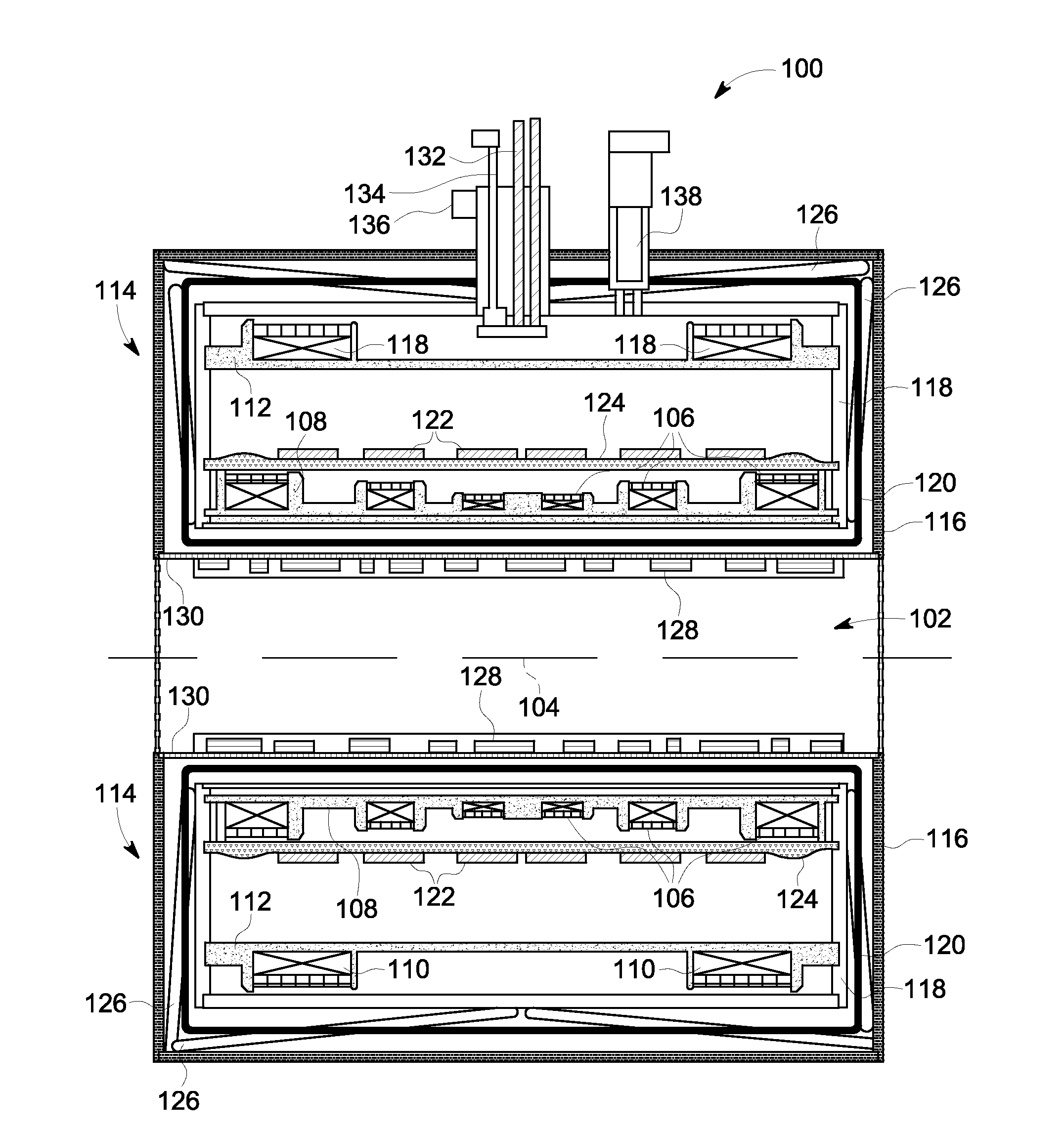
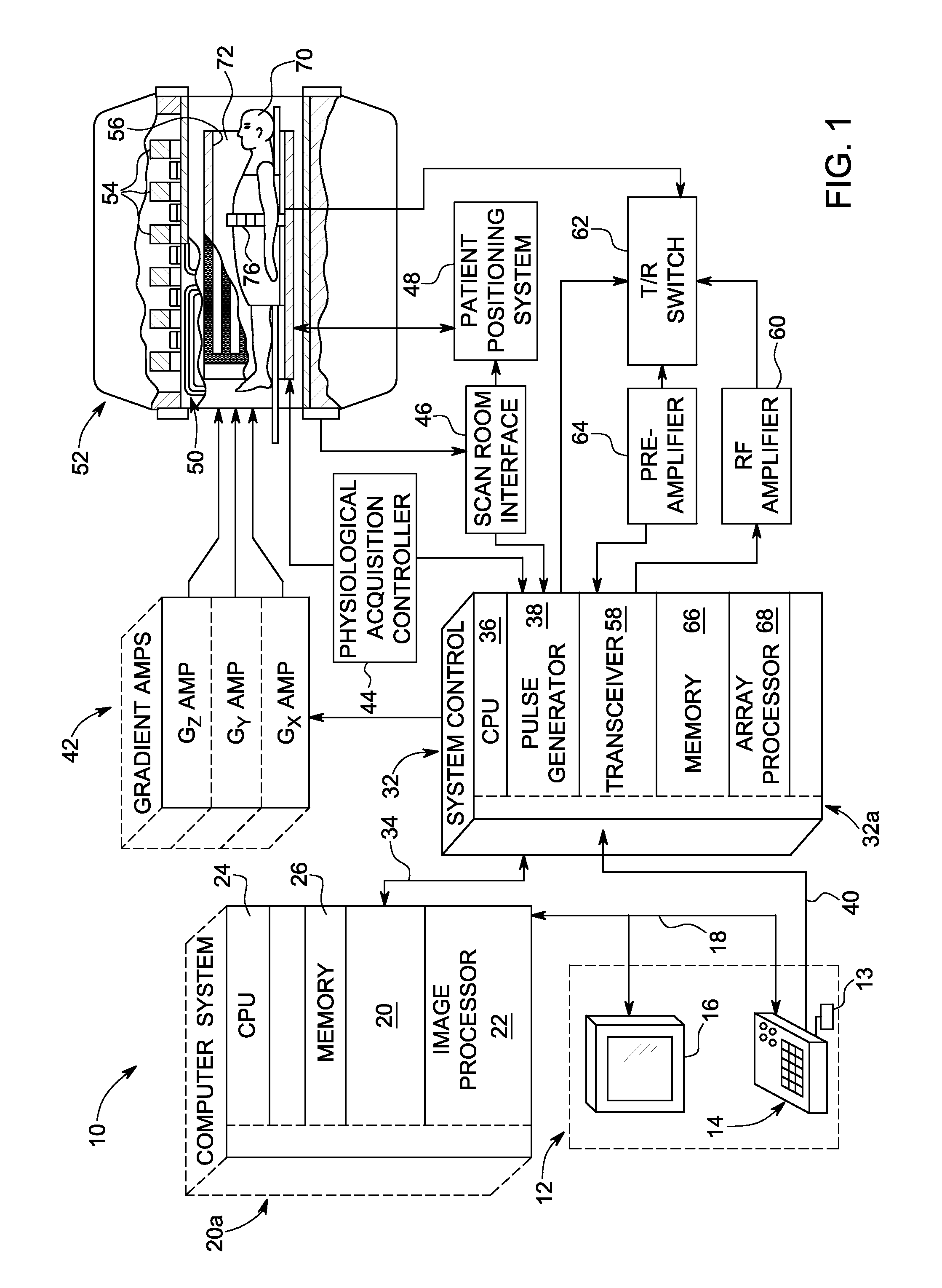
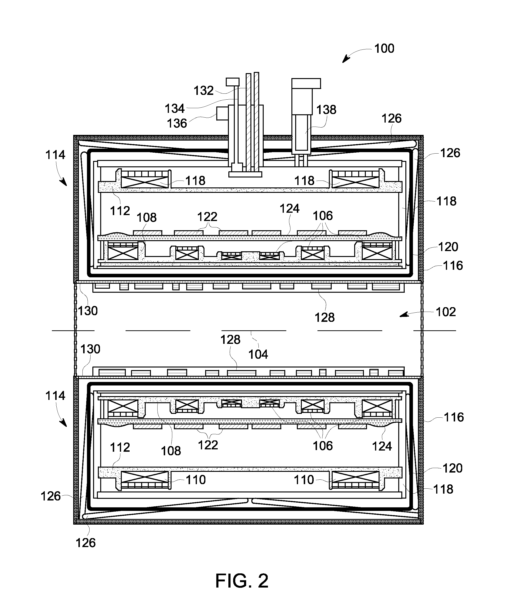
[0026]Referring to FIG. 1, the major components of a magnetic resonance imaging (MRI) system 10 incorporating an embodiment of the invention are shown. The operation of the system is controlled for certain functions from an operator console 12 which in this example includes a keyboard or other input device 13, a control panel 14, and a display screen 16. The console 12 communicates through a link 18 with a separate computer system 20 that enables an operator to control the production and display of images on the display screen 16. The computer system 20 includes a number of modules which communicate with each other through a backplane 20a. These modules include an image processor module 22, a CPU module 24 and a memory module 26, known in the art as a frame buffer for storing image data arrays. The computer system 20 communicates with a separate system control 32 through a high speed serial link 34. The input device 13 can include a mouse, joystick, keyboard, track ball, touch activ...


PUM

PropertyMeasurementUnit
vibrational frequencyaaaaaaaaaa

Abstract

A system and method for magnetic field distortion compensation includes a cryostat for a magnetic resonance imaging (MRI) system. The cryostat includes a vacuum casing having a vacuum therein. A cryogen vessel is disposed within the casing, the vessel having a coolant therein. A thermal shield is disposed between the vacuum casing and the cryogen vessel. An eddy current compensation assembly is disposed within the casing. The eddy current compensation assembly includes a plurality of electrically conductive loops formed on one of the vacuum casing, the cryogen vessel, and the thermal shield and constructed to mitigate vibration-induced eddy currents in the MRI system.

Description

CROSS REFERENCE TO RELATED APPLICATION[0001]The present application is a continuation-in-part of and claims priority to U.S. Non-Provisional application Ser. No. 13 / 690,312, filed Nov. 30, 2012, which claims priority to U.S. Provisional Application Ser. No. 61 / 577,805, filed Dec. 20, 2011, the disclosures of which are incorporated herein incorporated by reference.FIELD OF THE INVENTION[0002]Embodiments of the invention relate generally to a magnetic resonance imaging (MRI) system and in particular to a system and apparatus for compensating for magnetic field distortion caused by mechanical vibrations in the MRI system.BACKGROUND OF THE INVENTION[0003]Magnetic resonance imaging (MRI) is a medical imaging modality that can create pictures of the inside of a human body without using x-rays or other ionizing radiation. MRI uses a powerful magnet to create a strong, uniform, static magnetic field (i.e., the “main magnetic field”). When a human body, or part of a human body, is placed in ...

Claims


Application Information

Patent Timeline
Patent Type & Authority Applications(United States)
IPC IPC(8): G01R33/3875G01R33/34
CPCG01R33/3804G01R33/3815Y10T29/49014G01R33/3875G01R33/34023G01R33/56518H01F6/04H01F6/06
Inventor SHEN, WEIJUNHAVENS, TIMOTHY JOHNJIANG, LONGZHISAHA, SAIKATGRONEMEYER, BENJAMIN JACOBMOGATADAKALA, VENKATA KISHORE
Owner GENERAL ELECTRIC CO
Learn More