
System and method for low speed control of polyphase ac machine

a polyphase ac machine and low speed control technology, applied in the direction of electric generator control, luminescence/biological stain preparation, therapy, etc., can solve the problems of high inefficiency, switching loss, and converters that are typically not operated, so as to maximize the efficiency of the power generation system and efficiently operate

Inactive Publication Date: 2013-06-20
ENSYNC
View PDF11 Cites 10 Cited by
  • Summary
  • Abstract
  • Description
  • Claims
  • Application Information

AI Technical Summary

Benefits of technology

The present invention relates to improving power capture in wind turbines by using a power converter to convert the power generated by the alternator of the wind turbine into a suitable AC current. The power converter operates in multiple operating modes, utilizing both synchronous and non-synchronous control methods, to extend the operating range of the power converter. This allows for efficient capture of power during low wind speed operation. The non-synchronous control method includes a variable frequency pulse width modulation (PWM) including dead time control approach that reduces losses associated with switching of solid state power devices during power conversion. The power converter is configured to operate with wind turbines and has a reduced loss of power in low wind speed operation. The synchronous control method is used at higher wind speeds to transfer power to the grid or electrical load. The power converter uses a combination of dead time compensation and minimization of losses to capture low power levels and minimize converter losses in this area of very low power utilization. The multiple operating modes extend the operating range of the converter without excessive current spiking while not adding any detrimental effects to the wind generator.

Problems solved by technology

Because conventional switching methods are highly inefficient at low power levels, resulting in switching losses that exceed power production, the power converter is typically not operated during periods of low power production.

Method used


Image

  • System and method for low speed control of polyphase ac machine
  • System and method for low speed control of polyphase ac machine
  • System and method for low speed control of polyphase ac machine

Examples


Embodiment Construction

[0038]The various features and advantageous details of the subject matter disclosed herein are explained more fully with reference to the non-limiting embodiments described in detail in the following description.

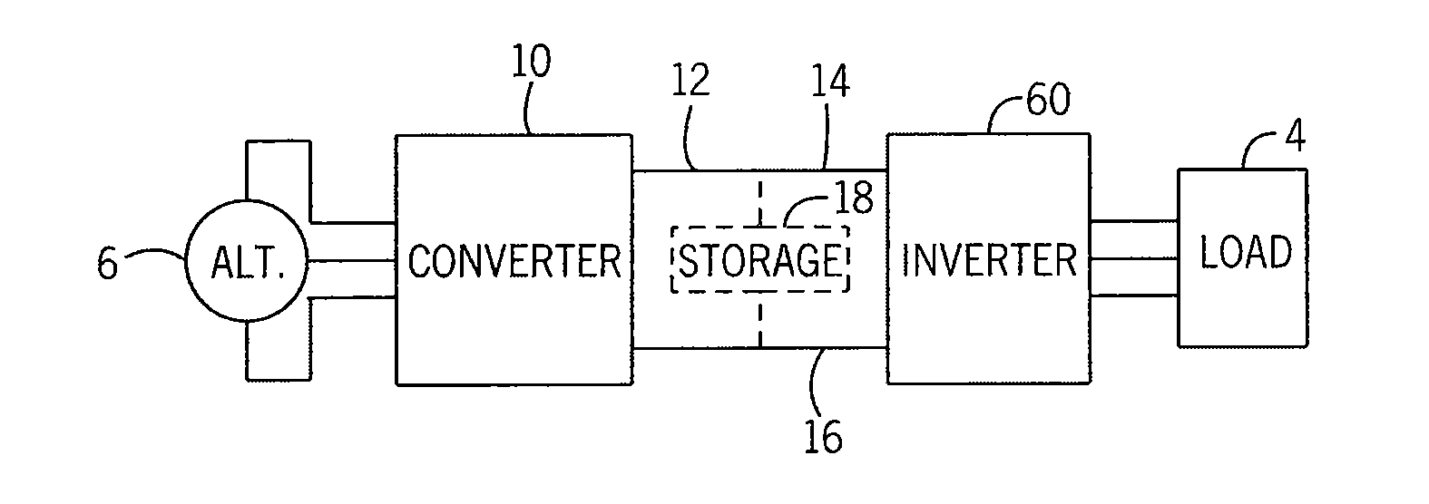
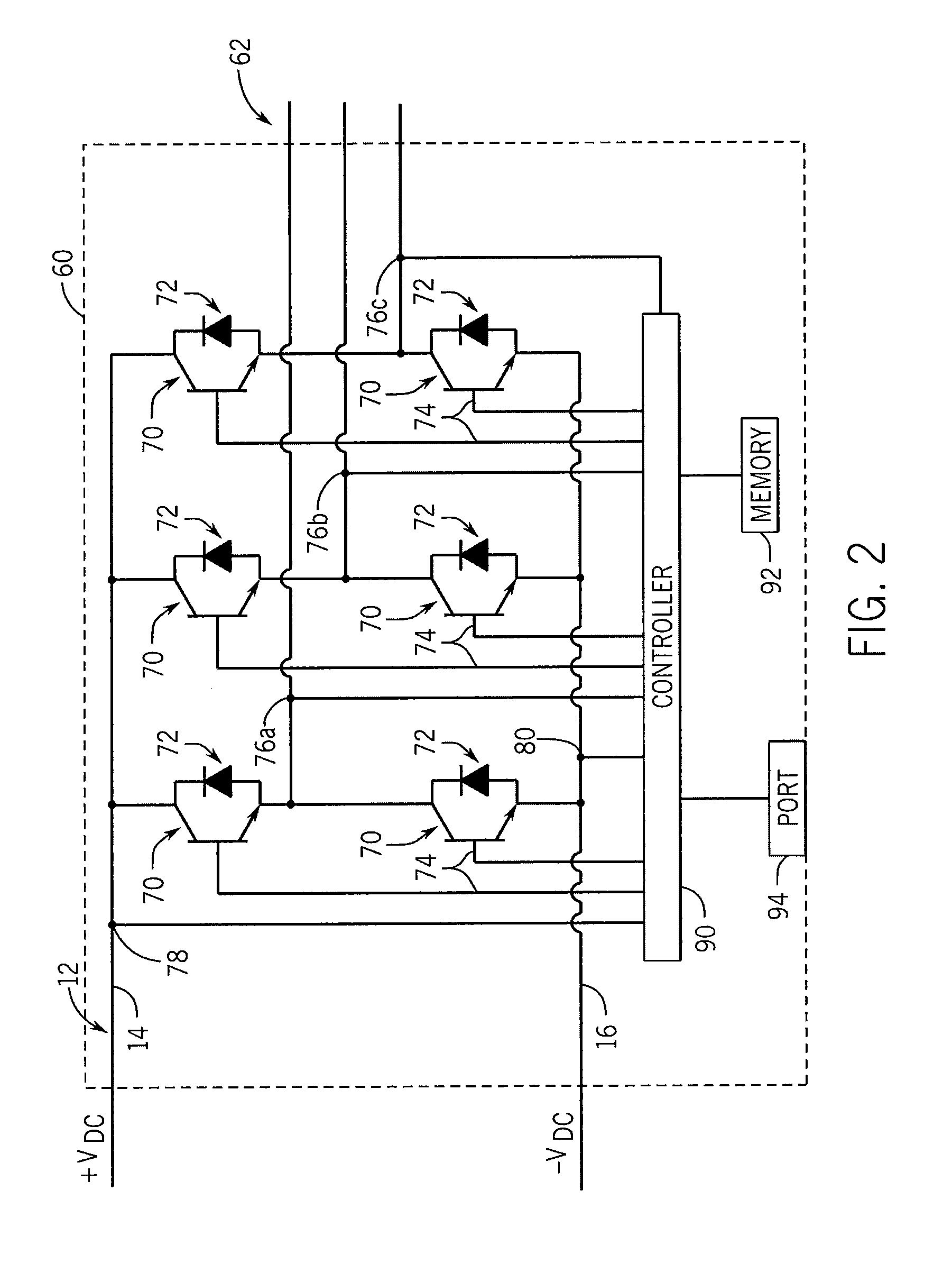
[0039]Turning initially to FIG. 1, an exemplary converter 10 incorporating one embodiment of the present invention is illustrated. The converter 10 includes three input terminals, T1-T3, configured to receive input voltages. Each of the input terminals, T1-T3, of the illustrated embodiment is configured to receive one phase of a multi-phase voltage, V1-V3, generated by an alternator 6. The alternator 6 may generate, for example, three phase alternating current (AC) power. An input filter 28 is connected in series with each of the terminals, T1-T3.

[0040]The converter 10 receives the multiphase AC input voltage, V1-V3, at the terminals, T1-T3, and outputs a desired DC voltage, Vdc, present on a DC bus 12 using switching devices, 20 and 21. The DC bus 12 includes a positive rai...


PUM


Abstract

A power converter configured to improve power capture in a wind turbine during low wind speed operation is disclosed. The power converter converts the power generated by the alternator of the wind turbine into a suitable AC current for delivery to a utility grid or to an electric load independent of the utility grid. The power converter is configured to operate in multiple operating modes, utilizing both synchronous and non-synchronous control methods, to extend the operating range of the power converter. During non-synchronous operation, the power converter utilizes a modulation routine that may either vary the dead-time compensation period during a constant modulation period or vary the modulation period with a constant on-time. A seamless transfer between non-synchronous and synchronous control methods with low total harmonic distortion (THD) improves the range of power generation for wind generators.

Description

CROSS-REFERENCE TO RELATED APPLICATIONS[0001]This application claims priority to U.S. provisional application Ser. No. 61 / 577,447, filed Dec. 19, 2011, the entire contents of which is incorporated herein by reference.BACKGROUND OF THE INVENTION[0002]The subject matter disclosed herein relates to power converters and, more specifically, to improved control of and / or power conversion from polyphase alternating current (AC) machines during low speed operation.[0003]In recent years, increased demands for energy and increased concerns about supplies of fossil fuels and their corresponding pollution have led to an increased interest in renewable energy sources. Two of the most common and best developed renewable energy sources are photovoltaic energy and wind energy. Other renewable energy sources may include fuel cells, hydroelectric energy, tidal energy, and biofuel or biomass generators. However, using renewable energy sources to generate electrical energy presents a new set of challen...

Claims


Application Information

Patent Timeline
Patent Type & Authority Applications(United States)
IPC IPC(8): H02M5/453A61K33/24
CPCH02M5/453H02M7/219Y02E10/763H02J3/386Y02E10/76A61K33/24A61K49/005A61N5/062H02P23/03H02P2101/15H02P6/182A61K41/0057B82Y5/00B82Y30/00B82Y40/00C09K11/7773H02J2300/28H02J3/381H02J3/44H02P9/48H02M7/162
Inventor REICHARD, JEFFREY A.JOBE, NATHANLAUBENSTEIN, THOMAS ALAN
Owner ENSYNC
Learn More