
Intrinsically Safe Energy Limiting Circuit

a technology of energy limiting circuit and intrinsically safe, applied in the direction of emergency protective circuit arrangement, emergency protection circuit arrangement, etc., can solve the problem of increasing the complexity of evaluation of intrinsically safe circuit, limiting current to a safe value, and each conventional energy limiting barrier has its own fuse, etc. problem, to achieve the effect of protecting the fus

Active Publication Date: 2013-06-20
SIEMENS AG
View PDF7 Cites 17 Cited by
  • Summary
  • Abstract
  • Description
  • Claims
  • Application Information

AI Technical Summary

Benefits of technology

The invention describes a circuit where a fuse is placed before a DC-to-DC converter and protected by an electronic current limiter. This arrangement makes it easy to place the fuse in the circuit and keeps it separate from other components. The technical effect of this is that it provides a more reliable and safe way to protect the circuit from overcurrent events that might cause damage or malfunction.

Problems solved by technology

Furthermore, the current is limited to a safe value by a melting fuse between the power source and the zener barrier.
However, it may be a disadvantage that each conventional energy-limiting barrier has its own fuse because intrinsically safe fuses are expensive.
Additionally, evaluation of the intrinsically safe circuit becomes more complex with two or more fuses, where the downstream devices are not separated electrically and the current is potentially shared between the fuses under normal or fault conditions.
This has the result of a difficult safety certification.
The practicality of keeping both sides of the fuse separated in the middle of a circuitry is much harder than having the fuse up front in the physical layout of the circuit.

Method used


Image

  • Intrinsically Safe Energy Limiting Circuit
  • Intrinsically Safe Energy Limiting Circuit
  • Intrinsically Safe Energy Limiting Circuit

Examples


Embodiment Construction

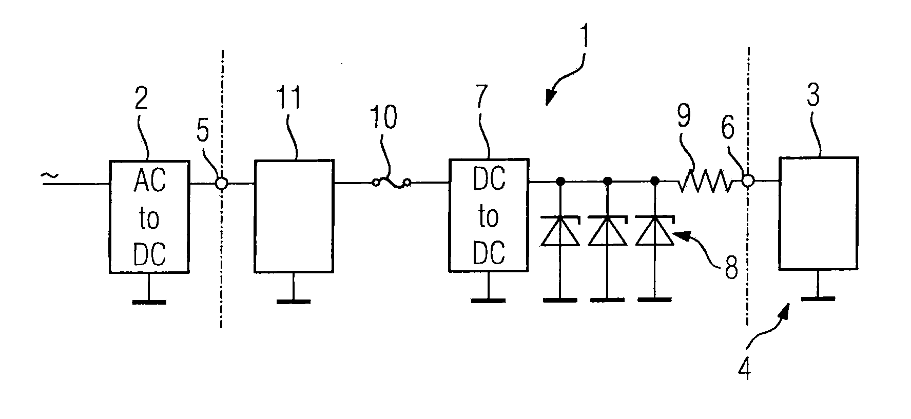
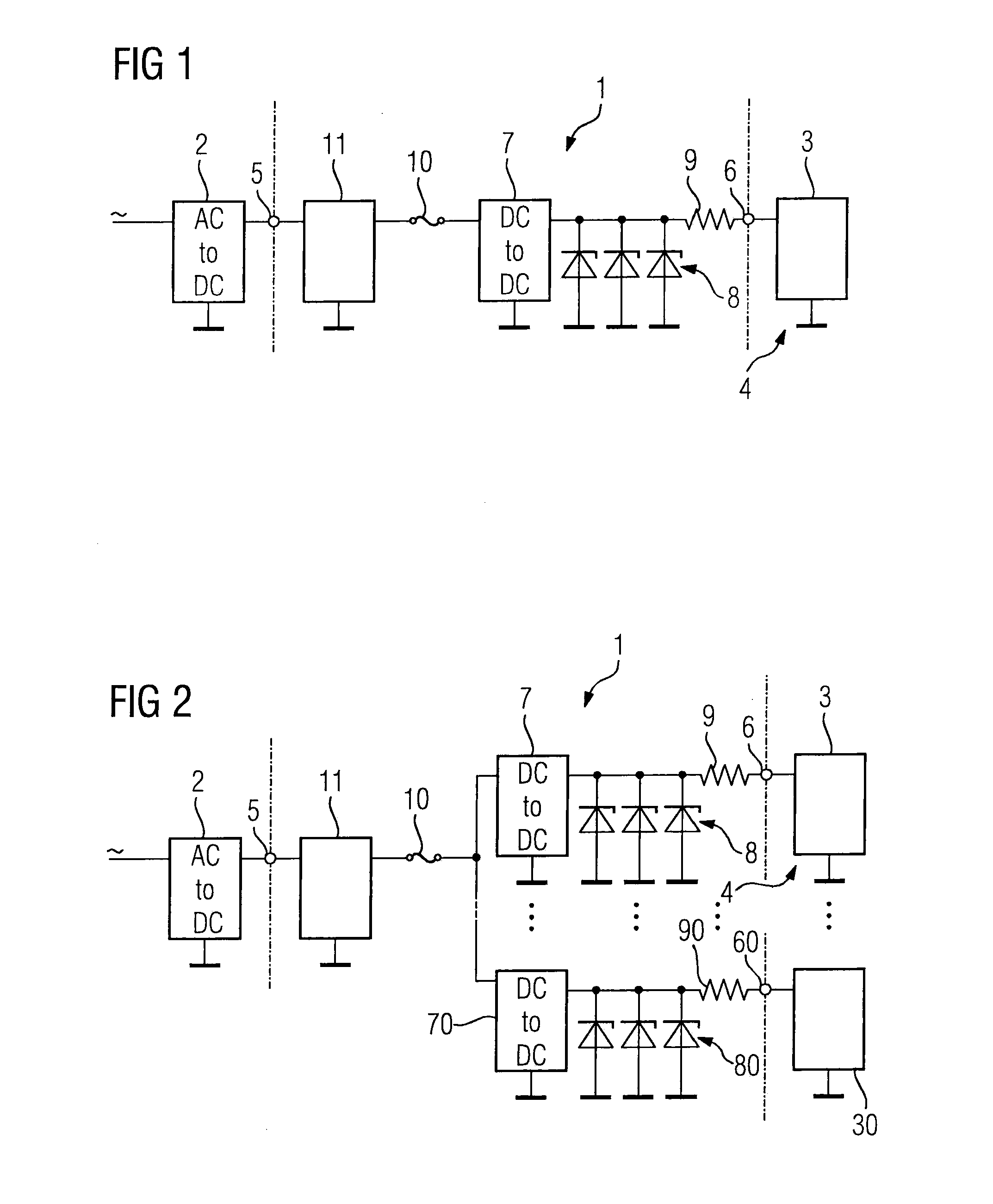
[0023]FIG. 1 shows an intrinsically safe (IS) energy limiting circuit 1 which is upstream connected to a DC power source 2 and downstream connected to an electrical load 3 to be powered from the DC power source 2. The electrical load 3 may be any device, system, circuit or part thereof which is subject to one or more IS standards, including but not limited to IEC 60079-11, FM 3610, and UL 913, and located in a hazardous area 4 where explosive and / or flammable gas may be present. The energy limiting circuit 1 and electrical load 3 may be separate devices or they may be integrated into one device. The DC power source 2 is a non-IS device or system that does not, or is not required to, meet IS standards.

[0024]The energy limiting circuit 1 has an input 5 to which the DC power source 2 is connected and an output 6 to which the electrical load 3 is connected. The upstream DC power source 2 provides a voltage which is higher than the voltage required by the downstream electrical load 3. Th...


PUM


Abstract

An intrinsically safe energy limiting circuit for connection between an upstream DC power source and a downstream electrical load powered from the upstream DC power source, wherein the circuit comprises from upstream to downstream an input to be connected to the DC power source, an electronic current limiter configured to limit a current through the circuit to a maximum value if the current reaches this value, a fuse designed to open at a current value greater than the maximum value, a DC-to-DC converter configured to convert a DC input voltage to a lower nominal DC output voltage, a zener barrier having a zener voltage higher than the DC output voltage, and an output for connection to the electrical load.

Description

BACKGROUND OF THE INVENTION[0001]1. Field of the Invention[0002]The invention relates to an intrinsically safe energy limiting circuit to be connected between an upstream DC power source and a downstream electrical load powered from that source.[0003]2. Description of the Related Art[0004]Intrinsic safety (IS) is a protection concept for safe operation of electrical equipment in explosive atmospheres and under irregular operating conditions. This concept, which is subject to a number of standards, relies on ensuring that the available electrical and thermal energy in the equipment is always low enough that ignition of the hazardous atmosphere cannot occur. In order to limit the electrical energy provided to the equipment, it is necessary to limit both current and voltage. The voltage is usually limited by a zener barrier. A series resistor between the zener barrier and the powered equipment provides instantaneous current limiting to prevent sparking or arcing when the current is int...

Claims


Application Information

Patent Timeline
Patent Type & Authority Applications(United States)
IPC IPC(8): H02H9/02
CPCH02H9/008H02H9/025H02H9/02
Inventor SCHMIDT, GLEN EUGENE
Owner SIEMENS AG
Learn More