Organic electroluminescent device
a technology of electroluminescent devices and organic electroluminescent devices, which is applied in the direction of static indicating devices, discharge tubes, instruments, etc., can solve the problems of non-uniform luminance in the luminescent zone of organic electroluminescent devices, and achieve the effect of increasing the aperture ratio and uniform illumination
- Summary
- Abstract
- Description
- Claims
- Application Information
AI Technical Summary
Benefits of technology
Problems solved by technology
Method used
Image
Examples
first embodiment
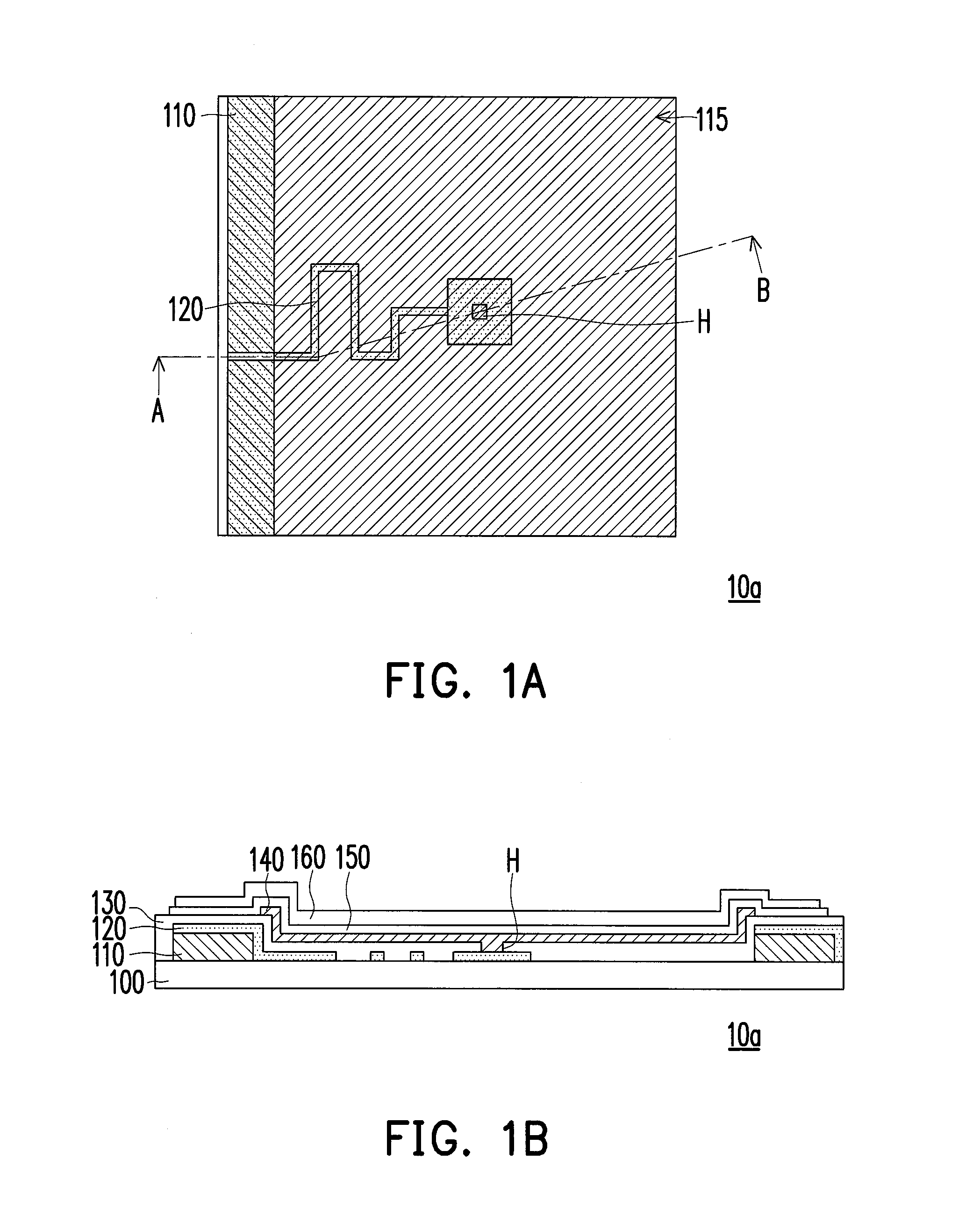
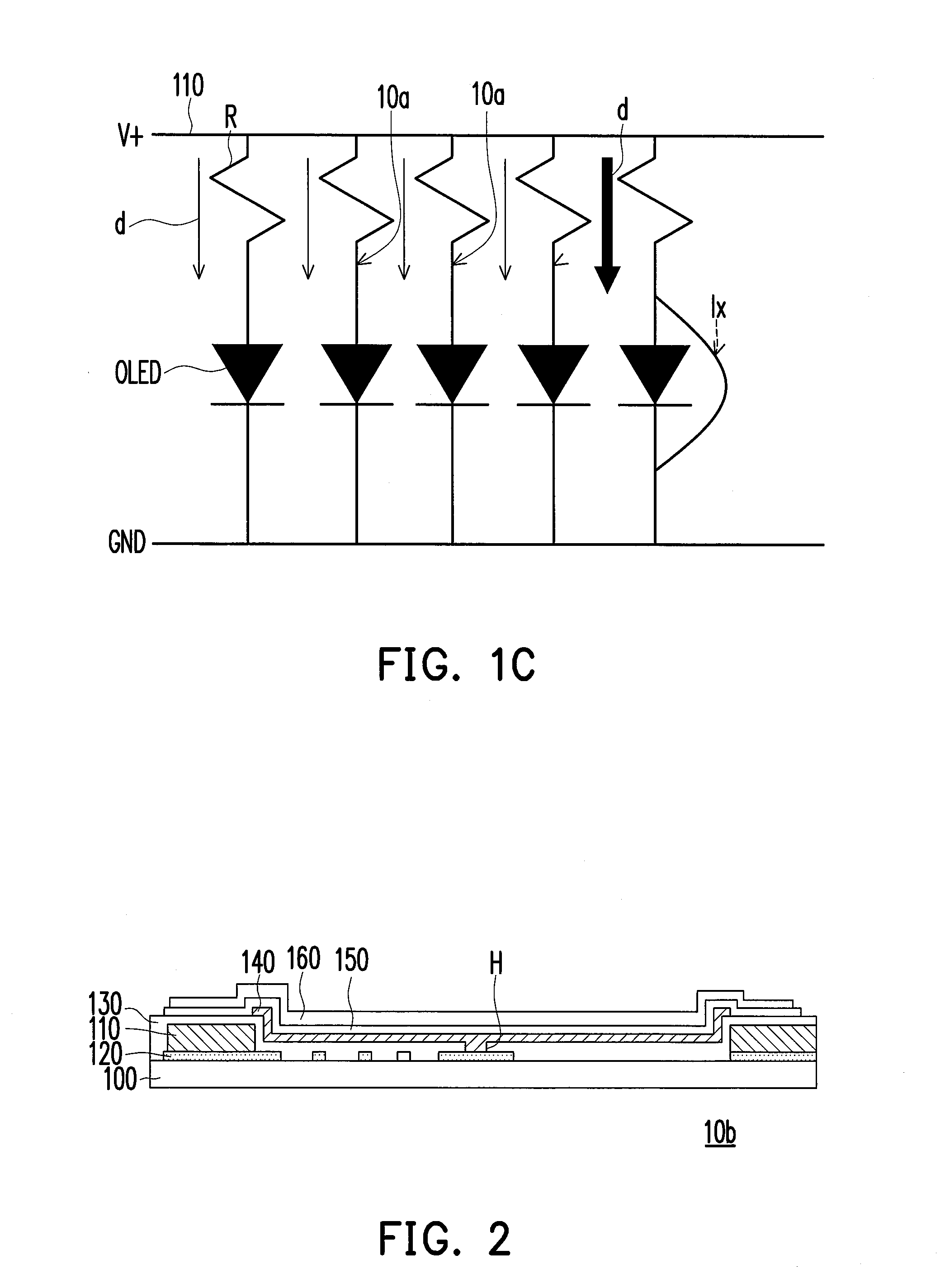
[0031]FIG. 1A is a schematic top view of an organic electroluminescent device in the first embodiment of the present invention, and FIG. 1B is a cross-sectional view of the organic electroluminescent device in FIG. 1A along a cross-sectional line A-B. Referring to FIG. 1A and FIG. 1B, the organic electroluminescent device 10a of this embodiment includes a substrate 100, an electrode line 110, a transparent impedance line 120, an insulating layer 130, a transparent electrode 140, an organic illumination layer 150 and an electrode 160. A structure formed by the transparent electrode 140, the organic illumination layer 150 and the electrode 160 of the organic electroluminescent device 10a is also called an organic luminescent unit. Besides, a luminescent zone 115 is formed between the two neighboring electrode lines 110. The transparent impedance line 120, the insulating layer 130 and the organic luminescent unit are disposed in the luminescent zone 115 to form an organic electrolumine...
second embodiment
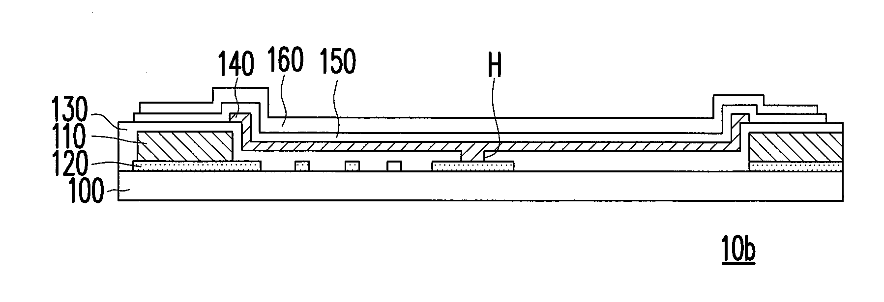
[0036]FIG. 2 is a schematic cross-sectional view of an organic electroluminescent device in the second embodiment of the present invention. Referring to FIG. 2, in the organic electroluminescent device 10b, the transparent impedance line 120 is disposed on the substrate 100 first, and the electrode line 110 is disposed on the transparent impedance line 120. In other words, in this embodiment, the transparent impedance line 120, the electrode line 110, the insulating layer 130, and the transparent electrode 140, the organic illumination layer 150 and the electrode 160 in the organic luminescent unit are disposed in sequence on the substrate 100. However, in the first embodiment, the electrode line 110 of the organic electroluminescent device 10a is formed on the substrate 100 first, and then the transparent impedance line 120 is formed, so that the transparent impedance line 120 covers the electrode line 110.
third embodiment
[0037]FIG. 3A is a schematic top view of an organic electroluminescent device in the third embodiment of the present invention, and FIG. 3B is a cross-sectional view of the organic electroluminescent device in FIG. 3A along a cross-sectional line A-B. Referring to FIG. 3A and FIG. 3B, the organic electroluminescent device 10c includes a patterned transparent conductive layer 125, and a part of the patterned transparent conductive layer 125 overlaps the electrode line 110. The patterned transparent conductive layer 125 and the transparent impedance line 120 are located at the same layer, but the patterned transparent conductive layer 125 is only connected to one end of the transparent impedance line 120 away from the contact hole, where the patterned transparent conductive layer 125 is disposed in an area in the luminescent zone 115 surrounding the transparent impedance line 120, and a part of the patterned transparent conductive layer 125 overlaps the electrode line 110, as shown in...
PUM
 Abstract
Description
Claims
Application Information
 - R&D
- Intellectual Property
- Life Sciences
- Materials
- Tech Scout
- Unparalleled Data Quality
- Higher Quality Content
- 60% Fewer Hallucinations
Browse by: Latest US Patents, China's latest patents, Technical Efficacy Thesaurus, Application Domain, Technology Topic, Popular Technical Reports.
© 2025 PatSnap. All rights reserved.Legal|Privacy policy|Modern Slavery Act Transparency Statement|Sitemap|About US| Contact US: help@patsnap.com


