Illumination light source and two-dimensional image display using same
a light source and light source technology, applied in the direction of picture reproducers, picture reproducers using projection devices, instruments, etc., can solve the problems of difficult to increase the amplitude by a normal driving method, and the driving is not stabilized, so as to achieve uniform illumination of the screen or the lik
- Summary
- Abstract
- Description
- Claims
- Application Information
AI Technical Summary
Benefits of technology
Problems solved by technology
Method used
Image
Examples
first embodiment
[0022]One embodiment of the invention will now be described in detail with reference to the drawings.
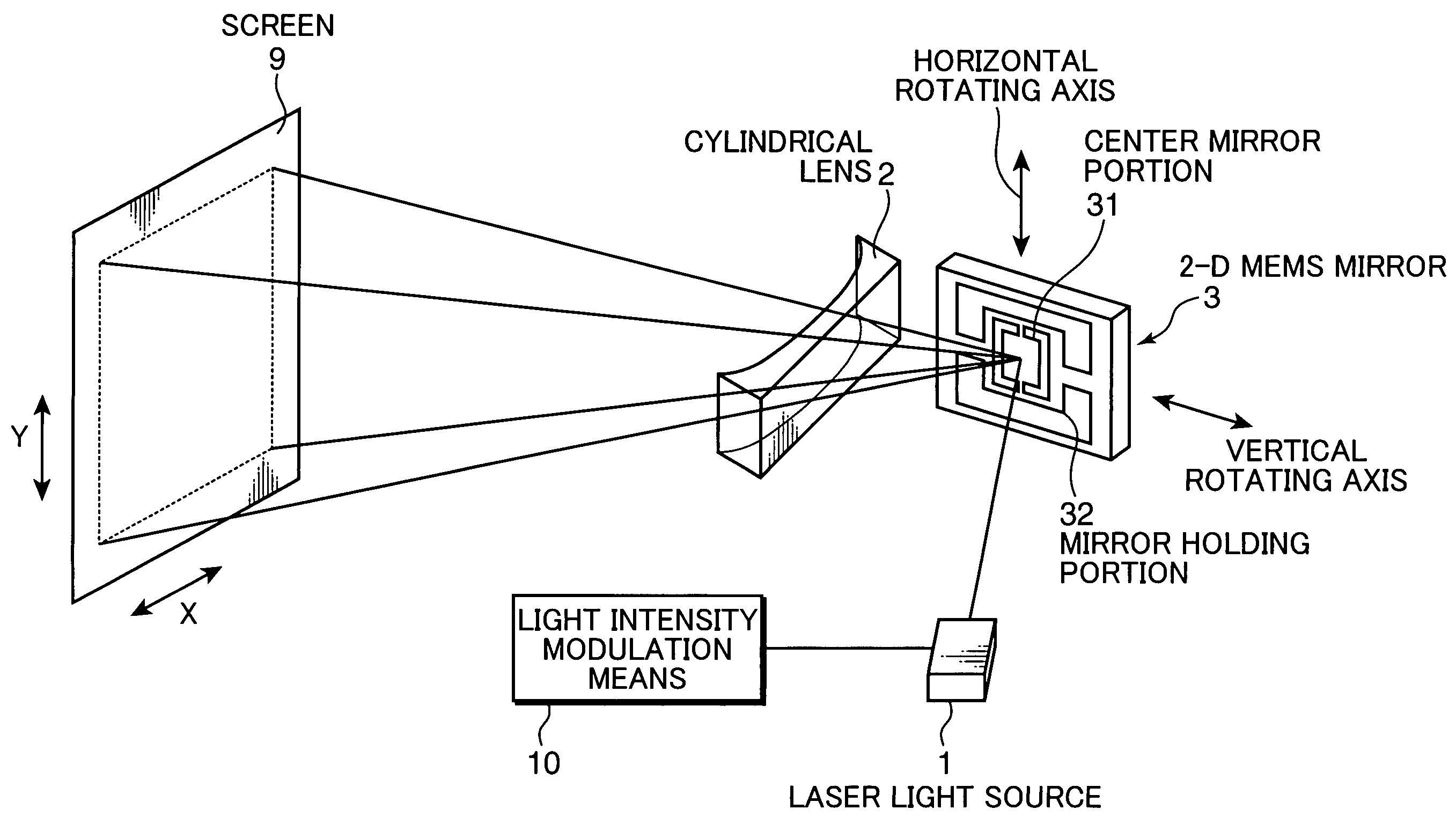
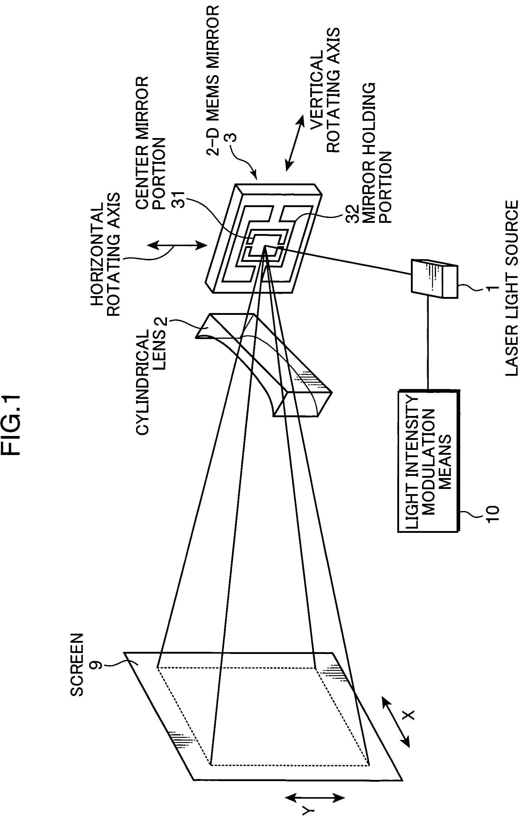
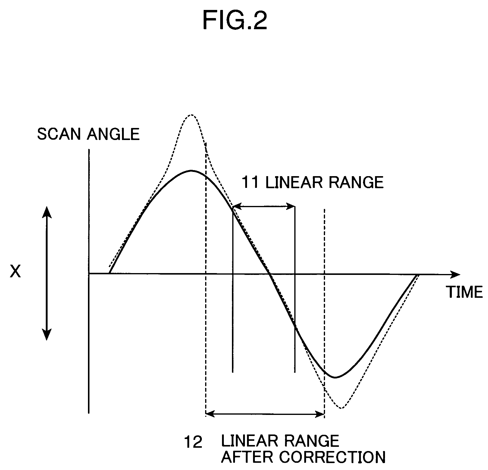
[0023]FIG. 1 is a view schematically showing the configuration of a 2-D image display device of the invention. Light from a laser light source 1, which is modulated in intensity by light intensity modulation means 10 according to an input video signal, irradiates a 2-D MEMS mirror 3. The 2-D MEMS mirror 3 is a movable mirror made of silicon crystal having a thickness of about 10 μm. It is held at a position afloat from the bottom surface substrate by the etching technique. A center mirror portion 31 is connected to mirror holding portions 32 in the vertical direction by means of beams. Also, the mirror holding portions 32 are supported on beams in the horizontal direction. Under the center mirror portion 31, electrodes partitioned to right and left portions are formed on the bottom surface substrate. By applying a voltage between the center mirror portion 31 and the electrodes on the...
second embodiment
[0039]FIG. 5 shows another embodiment of the correction optical system used in the invention. FIG. 5 shows the optical configuration of the optical system in FIG. 1 in a direction corresponding to the X-direction. Herein, a free-form mirror (one embodiment of the correction optical system) 5 is used as the scan angle correction optical system. The free-form mirror 5 has a concave surface shape at the center, that is, a region where the beam scan angle is small, and a convex surface shape in the peripheral portion, that is, a region where the beam scan angle is large. The scan angle increases rapidly when a beam passes by the peripheral portion of the free-form mirror 5. It is thus possible to suppress the brightness distribution caused by a difference of the scan rates.
[0040]Also, the light shield means as described above can be also provided to the free-form mirror 5. In this case, for example, metal or other materials (carbon black or the like) may be directly formed on the surfac...
third embodiment
[0041]FIG. 6 shows one embodiment when a 2-D image display device is constructed from a combination of the illumination light source of the invention and a projection optical system. In the configuration of the second embodiment, an image is formed directly on the screen by scanning light from the laser light source 1 two-dimensionally while modulating the light in intensity. On the contrary, in this embodiment shown in FIG. 6, the laser light source 1 is illuminated at a constant quantity of light, and a spatial light modulation element 6 is illuminated using the 2-D MEMS mirror 3 and a scan angle correction optical system 4. For example, a liquid crystal panel in which optical switches using TN liquid crystal elements are aligned two-dimensionally in multiple arrays is used as the spatial light modulation element 6. The spatial light modulation element 6 is illuminated with a uniform brightness distribution, and a 2-D image formed by passing through the spatial light modulation el...
PUM
 Abstract
Description
Claims
Application Information
 - R&D
- Intellectual Property
- Life Sciences
- Materials
- Tech Scout
- Unparalleled Data Quality
- Higher Quality Content
- 60% Fewer Hallucinations
Browse by: Latest US Patents, China's latest patents, Technical Efficacy Thesaurus, Application Domain, Technology Topic, Popular Technical Reports.
© 2025 PatSnap. All rights reserved.Legal|Privacy policy|Modern Slavery Act Transparency Statement|Sitemap|About US| Contact US: help@patsnap.com


