
Sliding member and fluid dynamic pressure bearing apparatus

a technology of fluid dynamic pressure bearing and sliding member, which is applied in the direction of sliding contact bearings, mechanical devices, liquid cushion bearings, etc., can solve the problems of increasing manufacturing costs, and achieve the effects of satisfactory frictional wear resistance, sufficient adhesiveness, and simple structur

Inactive Publication Date: 2013-06-20
MINEBEAMITSUMI INC
View PDF6 Cites 1 Cited by
  • Summary
  • Abstract
  • Description
  • Claims
  • Application Information

AI Technical Summary

Benefits of technology

The present invention provides a sliding member with a protective film that has excellent resistance to friction and good adhesiveness to the substrate, regardless of its simple structure. The protective film has a metal base layer, a low-hardness diamond-like carbon layer, and a high-hardness diamond-like carbon layer. This results in a long service life for the sliding member, as the protective film can withstand long periods of use and maintains its effectiveness.

Problems solved by technology

However, providing a plurality of base layers below the diamond-like carbon layer requires a plurality of kinds of raw materials and a complicated manufacturing process, which in turn increase the manufacturing cost.

Method used


Image

  • Sliding member and fluid dynamic pressure bearing apparatus
  • Sliding member and fluid dynamic pressure bearing apparatus
  • Sliding member and fluid dynamic pressure bearing apparatus

Examples


first embodiment

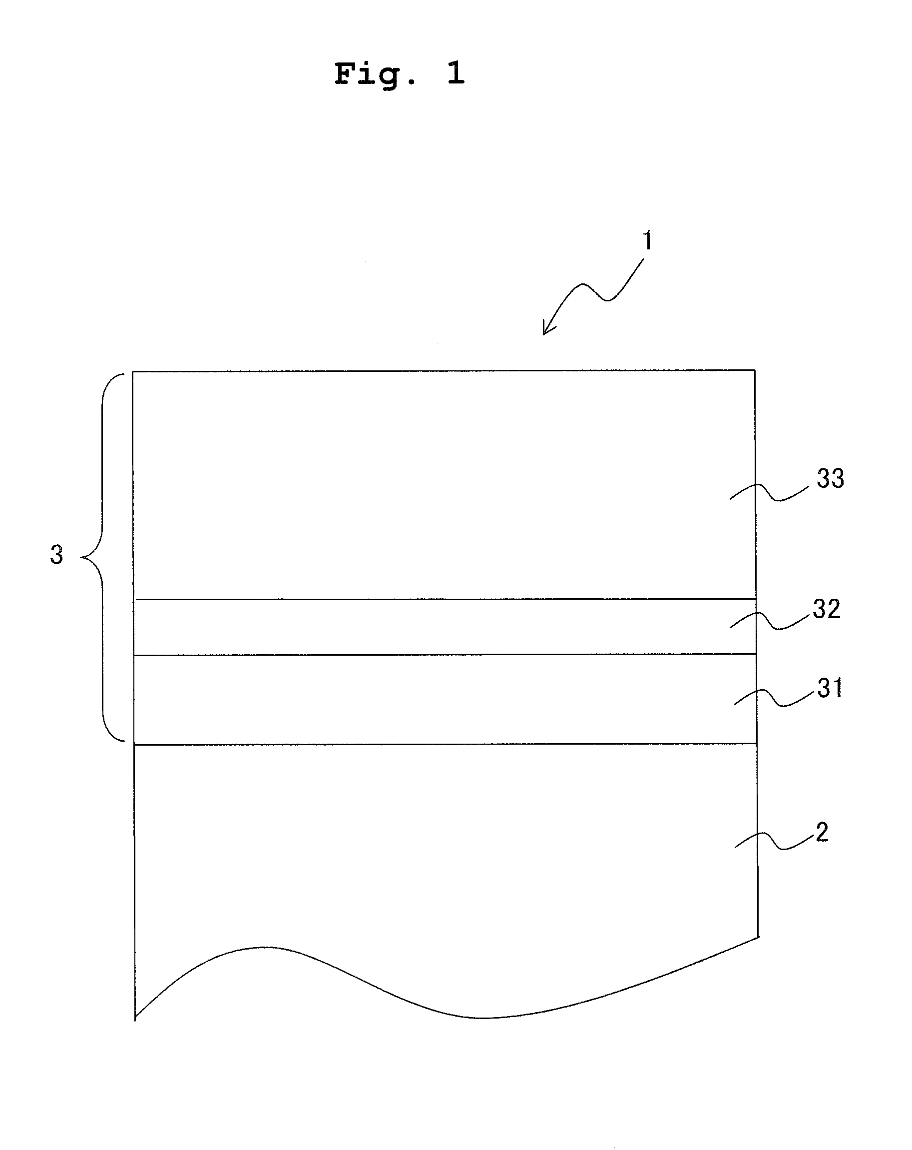
[0024]An explanation will be given about a sliding member as a first embodiment of the present invention. As shown in FIG. 1, a sliding member 1 of the first embodiment has a substrate 2 and a protective film 3 provided on the substrate 2. It is possible to use, as the substrate 2, variety kinds of members or materials depending on the application for which the sliding member 1 is to be used. However, a material for a substrate of a sliding member which is used in a fluid dynamic pressure bearing apparatus is mainly preferable. Such a material for the substrate is exemplified by steel materials which are highly reliable and which can be processed with high precision; among such steel materials, stainless steel such as SUS430F having superior free-cutting property is preferable as the material for the sliding member used in the fluid dynamic pressure apparatus for a spindle motor of a hard disk drive.

[0025]The protective film 3 is composed only of a metal base layer 31 provided on th...

second embodiment

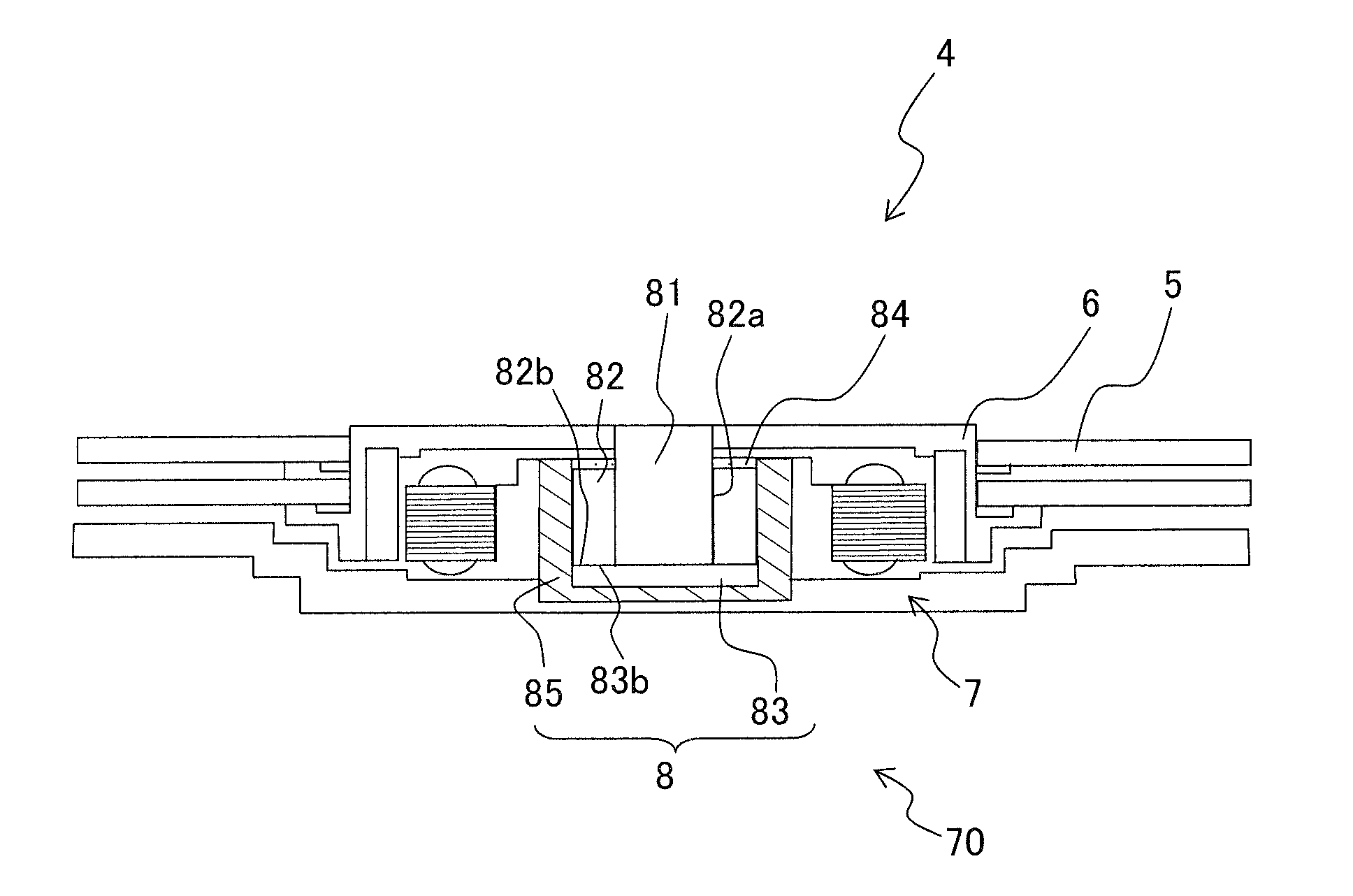
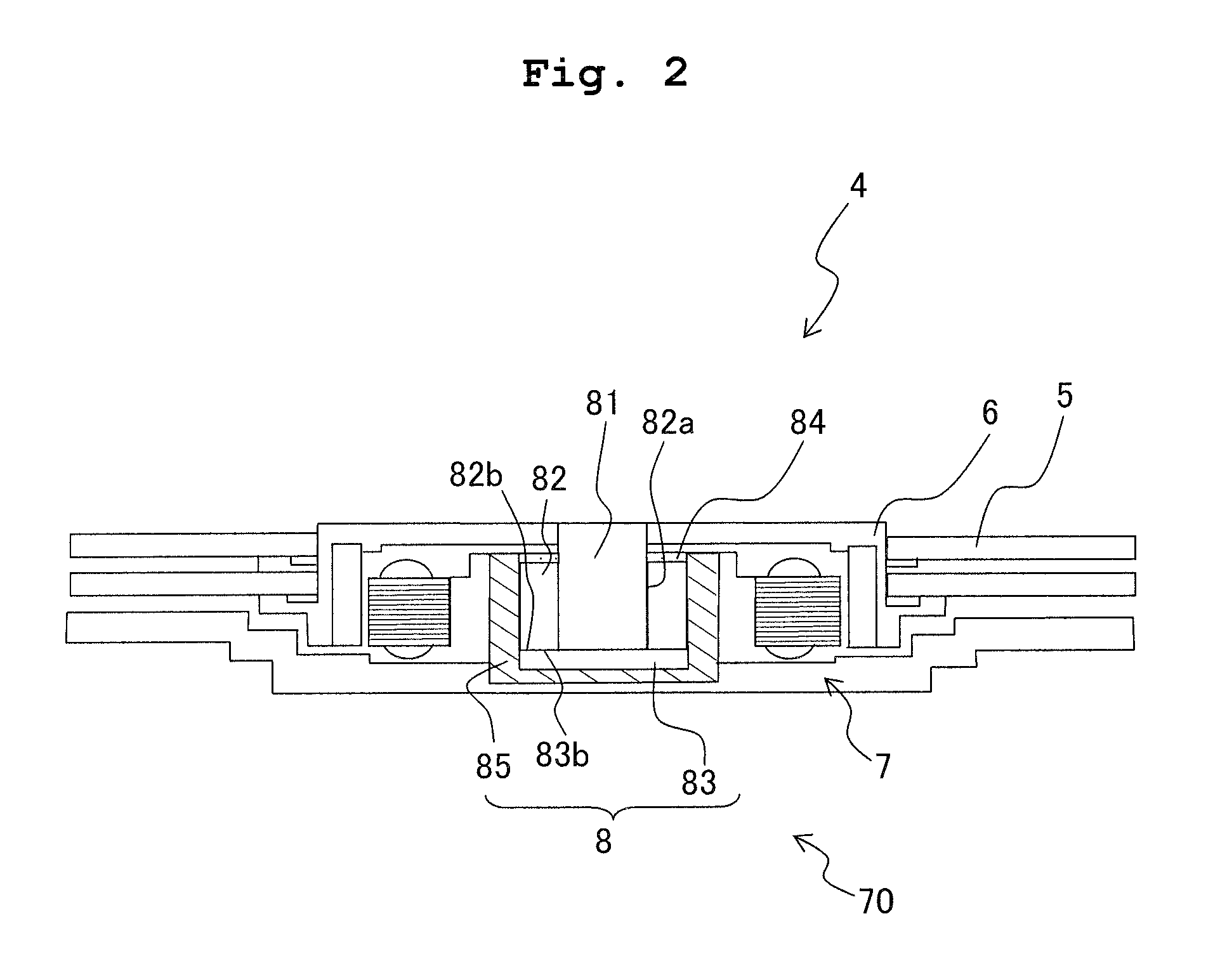
[0037]Regarding a fluid dynamic pressure bearing apparatus including the sliding member of the first embodiment, an explanation will be given considering as example a fluid dynamic pressure bearing apparatus for a spindle motor of a hard disk drive (HDD). A hard disk drive (HDD) 4 shown in FIG. 2 is mainly composed of a plurality of disks 5, a hub 6 supporting the disks 5, a spindle motor 7 having a permanent magnet, a coil, etc., and a fluid dynamic pressure bearing apparatus 8. An apparatus provided with the spindle motor 7 and the dynamic fluid pressure bearing apparatus 8 is also referred to as a spindle motor apparatus 70. As shown in FIGS. 2, 3A and 3B, the fluid dynamic pressure bearing apparatus 8 is mainly composed of a shaft 81, a cylinder-shaped bearing sleeve 82 having a through hole 82a which accommodates the shaft 81 therein, a disk-shaped thrust bearing 83 arranged at the lower end of shaft 81, a seal 84 and a housing 85 accommodating the above-described parts or comp...


PUM

PropertyMeasurementUnit
Fractionaaaaaaaaaa
Fractionaaaaaaaaaa
Pressureaaaaaaaaaa

Abstract

There is provided a sliding member including: a substrate; and a protective film provided on the substrate, wherein the protective film is composed only of a metal base layer provided on the substrate, a low-hardness diamond-like carbon layer provided as a single layer on the metal base layer, and a high-hardness diamond-like carbon layer provided as a single layer directly on the low-hardness diamond-like carbon layer. The sliding member has the protective film which has excellent frictional wear resistance property and satisfactory adhesion property to the substrate, regardless of having a simple structure.

Description

CROSS REFERENCE TO RELATED APPLICATION[0001]The present application claims priority from Japanese Patent Applications No. 2011-277468 filed on Dec. 19, 2011 and No. 2012-224766 filed on Oct. 10 2012 the disclosures of which are incorporated herein by reference in their entireties.BACKGROUND OF THE INVENTION[0002]1. Field of the Invention[0003]The present invention relates to a sliding member and a fluid dynamic pressure bearing apparatus using the sliding member.[0004]2. Description of the Related Art[0005]In the recent years, a fluid dynamic bearing (FDB) using an oil as fluid is used as the bearing for a motor. The fluid dynamic bearing has a long service life and causes less noise as compared with a ball bearing, and thus the fluid dynamic bearing is adopted in a hard disk drive, a heat exhaust fan, etc. In some cases, a high-lubricity coating is applied on a sliding surface of the fluid dynamic bearing, in addition to a dynamic-pressure generating groove formed on the sliding su...

Claims


Application Information

Patent Timeline
IPC IPC(8): F16C32/06H02K7/08
CPCF16C32/0662F16C32/0629H02K7/08F16C2370/12F16C2240/64F16C33/043F16C2223/60F16C2206/04F16C17/107
Inventor NIWA, SHINICHIFUJIMOTO, EIJIASAKAWA, TOSHIAKI
Owner MINEBEAMITSUMI INC
Learn More