Fixed cutter drill bit heel and back-ream cutter protections for abrasive applications

a technology of fixed cutter and protection, which is applied in the direction of cutting machines, manufacturing tools, other chemical processes, etc., can solve the problems of significant wear to the heel surface of fixed cutters, inability to justify their higher cost, and wear to the gage region of fixed cutters

Inactive Publication Date: 2013-06-20
SMITH INT INC
View PDF4 Cites 22 Cited by
  • Summary
  • Abstract
  • Description
  • Claims
  • Application Information

AI Technical Summary

Problems solved by technology

However, for drilling ultra abrasive formations, fixed cutter bits may cost significantly more than comparable roller cone bits and may become damaged beyond repair after a first run, such that their higher cost cannot be justified.
For example, substantial wear to the heel surfaces of fixed cutter bit blades may occur as the fixed cutter bit is reversed in the borehole, such as when back reaming or up drilling is performed, which may lead to wear of the gage region of the bit.
Once the gage region of the bit is worn away, the bit becomes incapable of maintaining the diameter of the borehole to be drilled, and thus unusable for additional runs.
Additionally, the bit and the PDC cutters may be subjected to substantial abrasive forces.
In some instances, impact, vibration, and erosive forces have caused drill bit failure due to loss of one or more cutters, or due to breakage of the blades.
While steel body bits may have toughness and ductility properties which make them resistant to cracking and failure due to impact forces generated during drilling, steel is more susceptible to erosive wear caused by high-velocity drilling fluids and formation fluids which carry abrasive particles, such as sand, rock cuttings and the like.
However, tungsten carbide and other erosion-resistant materials are relatively brittle.
During use, a thin coating of the erosion-resistant material may crack, peel off or wear, exposing the softer steel body, which is then rapidly eroded.
Fixed cutter bits are subjected to wear during drilling operations due to formation cuttings being drilled and the borehole wall hitting the outer surfaces of the bit.
Such wear may be particularly harmful in the gage region of the bit, as the gage region defines the diameter of the bit, and thus the size of the borehole wall.
Although attempts have been made at increasing the wear resistance in this area of fixed cutter bits, gage regions continue to experience wear and failure.
However, during drilling operations, particularly in unconsolidated highly abrasive formations or heavy oil drilling applications, such surface attachments may fall off, due to wear around the surface attachments or chipping, for example.

Method used


Image

  • Fixed cutter drill bit heel and back-ream cutter protections for abrasive applications
  • Fixed cutter drill bit heel and back-ream cutter protections for abrasive applications
  • Fixed cutter drill bit heel and back-ream cutter protections for abrasive applications

Examples


Embodiment Construction

[0027]In one aspect, embodiments disclosed herein relate generally to fixed cutter drill bits. More particularly, embodiments disclosed herein relate to fixed cutter drill bit heel and back-ream cutter protections for abrasive applications.

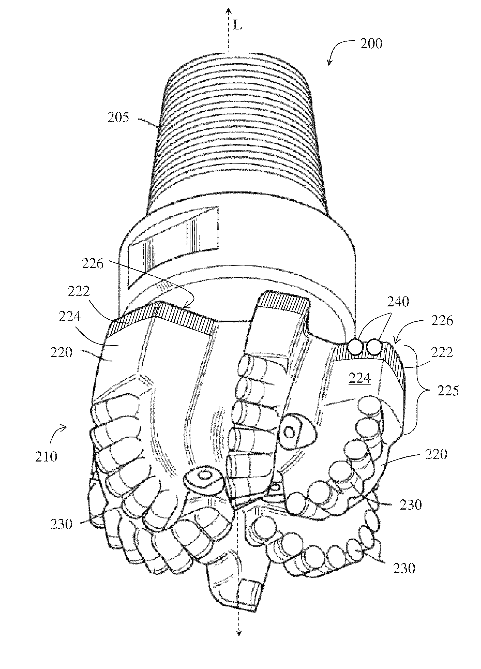
[0028]According to embodiments of the present disclosure, the heel surface and gage region of a fixed cutter bit may be provided with a unique combination of materials in order to add protection for that particular area of the bit, and thus increase the life of the bit. As described in more detail below, methods of increasing heel surface and gage protection may include forming a fixed cutter bit using a combination of back reaming elements and a matrix material different from other regions of the bit.

[0029]For example, a drill bit according to some embodiments of the present disclosure is shown in FIGS. 2A and 2B. As shown, a drill bit 200 has a longitudinal axis L, a threaded pin connection 205 and a cutting face 210. A plurality of blades 220 a...


PUM


Abstract

A method of manufacturing a fixed cutter drill bit may include loading a first matrix material of controlled thickness to at least a portion of a mold cavity corresponding to a heel surface of at least one blade; loading a second matrix material into the remaining portions of the mold cavity; heating the mold contents to form a matrix body of the fixed cutter drill bit; and disposing at least one back reaming element in at least one back reaming cutter pocket.

Description

CROSS-REFERENCE TO RELATED APPLICATION[0001]This application claims the benefit of U.S. Provisional Patent Application Ser. No. 61 / 577348 filed Dec. 19, 2011, which is incorporated herein by reference in its entirety.BACKGROUND[0002]Embodiments disclosed herein relate generally to fixed cutter drill bits. More particularly, embodiments disclosed herein relate to fixed cutter drill bit heel and back-ream cutter protections.BACKGROUND ART[0003]An earth-boring drill bit is typically mounted on the lower end of a drill string and is rotated by rotating the drill string at the surface or by actuation of downhole motors or turbines, or by both methods. When weight is applied to the drill string, the rotating drill bit engages the earth formation and proceeds to form a borehole along a predetermined path toward a target zone.[0004]Historically, there have been two main types of drill bits used for drilling earth formations, drag bits and roller cone bits. The term “drag bits” (also referre...

Claims


Application Information

Patent Timeline
Patent Type & Authority Applications(United States)
IPC IPC(8): E21B10/26
CPCE21B10/55E21B10/26E21B10/54
Inventor BURHAN, YURIHOFFMASTER, CARL M.LOCKWOOD, GREGORYSHEPHERD, RONDA S.O'LAIN, MATTHEWALLEN, BOBBY L.
Owner SMITH INT INC
Why Eureka
Try Eureka