Foil Stamping Apparatus

Inactive Publication Date: 2013-06-20
THE PROCTER & GAMBLE COMPANY
View PDF12 Cites 1 Cited by
  • Summary
  • Abstract
  • Description
  • Claims
  • Application Information

AI Technical Summary

Benefits of technology

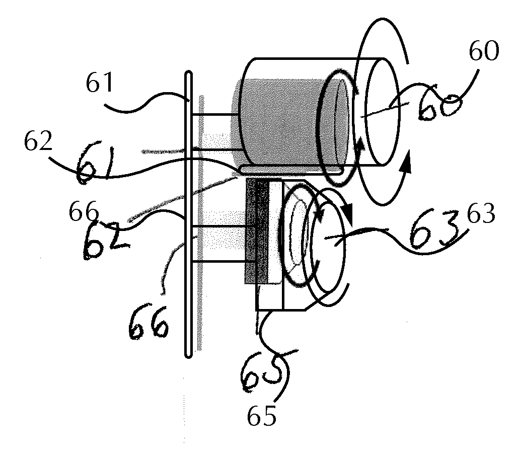
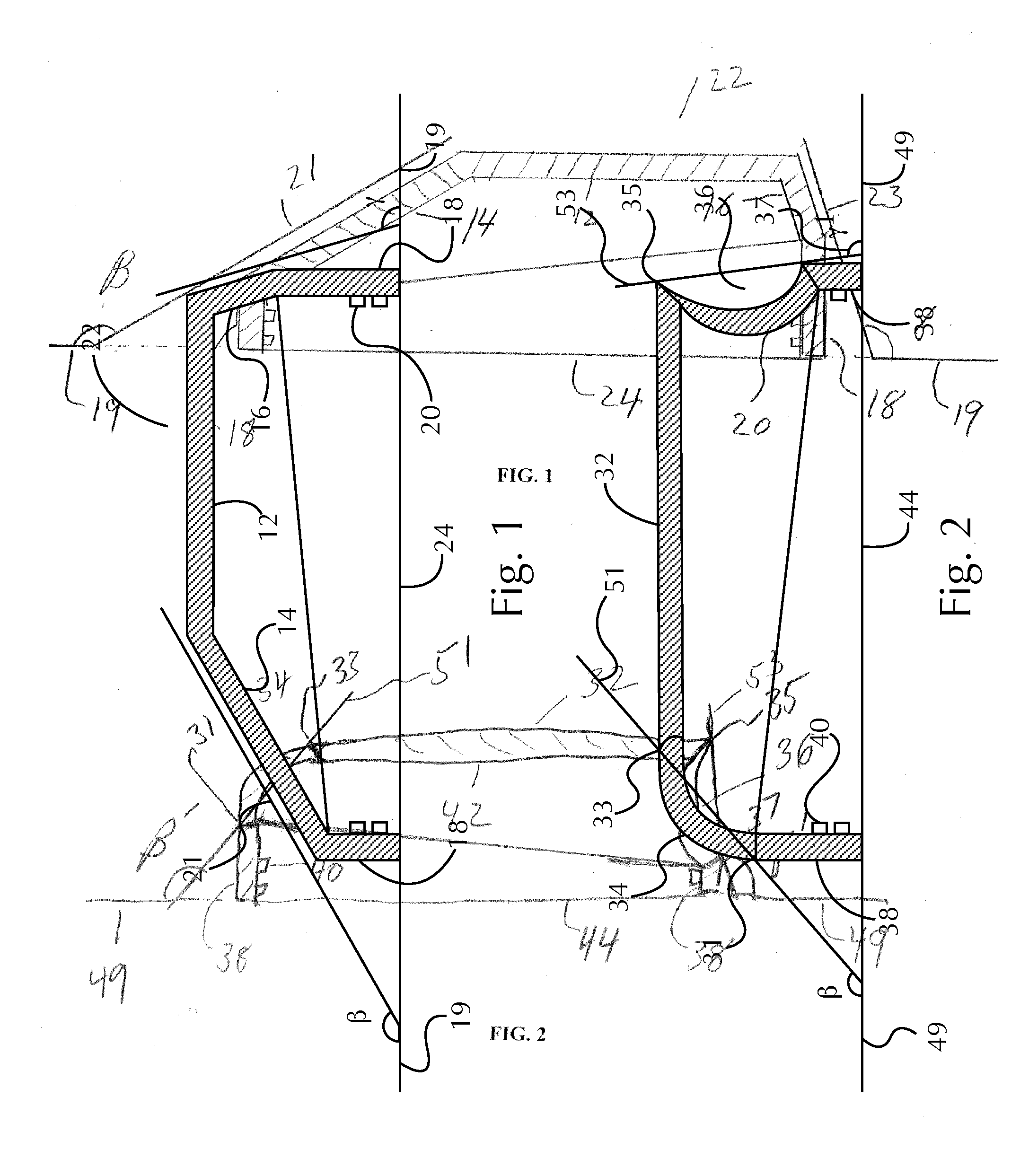
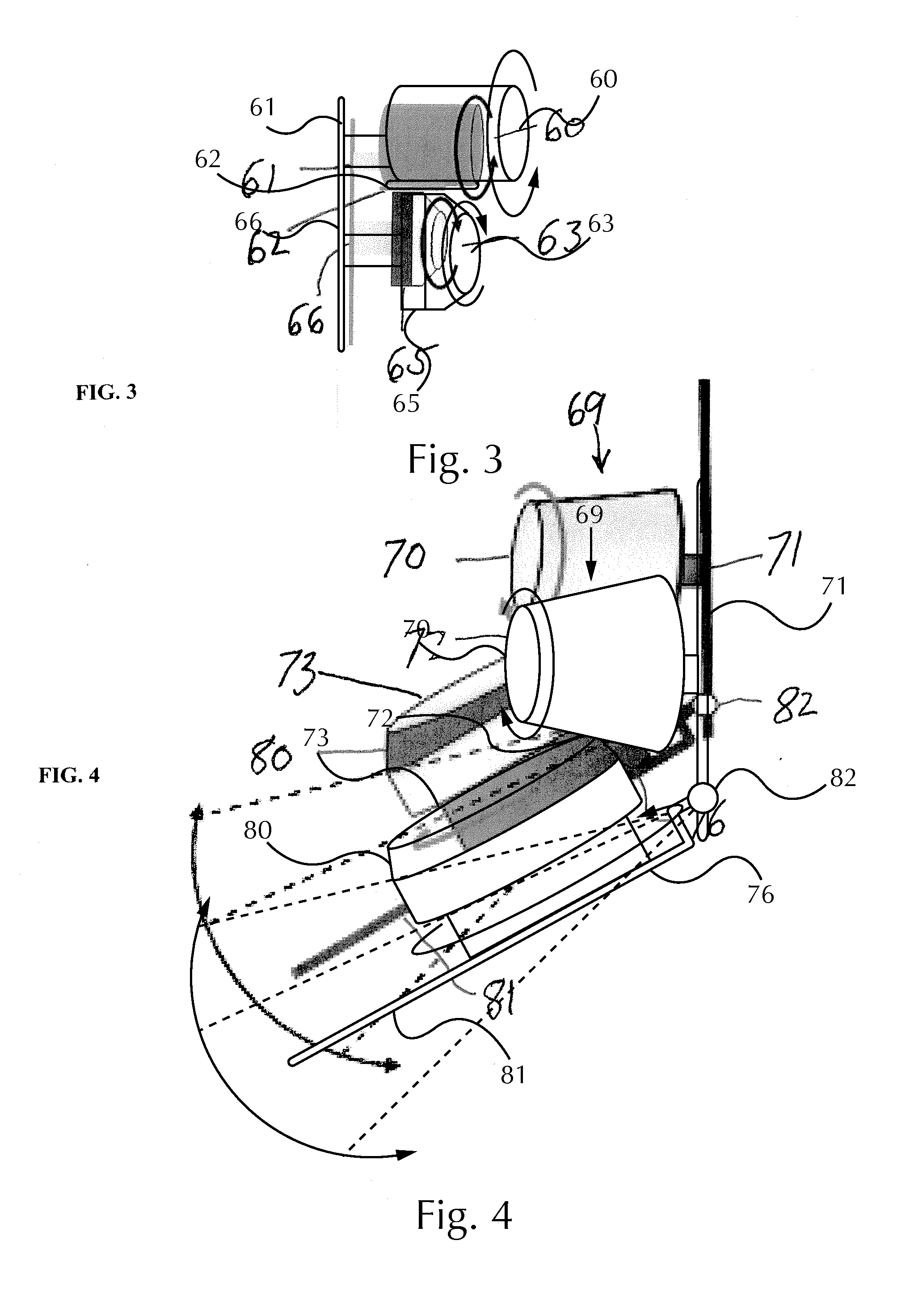
The present invention provides a way to quickly and easily coat parts with decorative or protective foil. This method works well with parts that have asymmetrical edges, and results in a uniform coating without any visible streaks or unevenness. This invention allows designers to create new part shapes and add multiple decorations on a single part.

Problems solved by technology

But these systems do not work parts with asymmetrical geometry as the mandrel cannot maintain constant contact with the asymmetrical part.
While virtually any shape can be stamped in this manner there is one inherent drawback to this process.
The foil is flat and when stamped onto a complex shape it necessarily must stretch and fold over onto itself resulting into uneven coverage.
Accordingly, there are geometrical limitations to this type of foil stamping.
But these soft, deformable stamp pads suffer from the same defects as discussed above.
This invariably leads to uneven coverage.

Method used


Image

  • Foil Stamping Apparatus
  • Foil Stamping Apparatus
  • Foil Stamping Apparatus

Examples


Embodiment Construction

[0019]The present invention may be understood more readily by reference to the following detailed description of illustrative and preferred embodiments. It is to be understood that the scope of the claims is not limited to the specific ingredients, methods, conditions, devices, or parameters described herein, and that the terminology used herein is not intended to be limiting of the claimed invention. Also, as used in the specification, including the appended claims, the singular forms “a,”“an,” and “the” include the plural, and reference to a particular numerical value includes at least that particular value, unless the context clearly dictates otherwise. When a range of values is expressed, another embodiment includes from the one particular value and / or to the other particular value. Similarly, when values are expressed as approximations, by use of the antecedent basis “about,” it will be understood that the particular values form another embodiment. All ranges are inclusive and ...


PUM

PropertyMeasurementUnit
Angleaaaaaaaaaa
Dimensionaaaaaaaaaa
Metallic bondaaaaaaaaaa

Abstract

An apparatus for coating a part that has an asymmetrical edge. The apparatus includes a film dispenser, a film retriever, a mandrel; and a part holder. Preferably one or both of the mandrel and the part holder move in an angular relationship to one another, and the film dispenser and the film retriever move co-operatively in at least two dimensions with respect to the part holder. There is further provided a film having a first edge and a second edge, and the film can be a decorative coating, a protective coating or combinations of these. The film dispenser holds the first edge of the film, the film is positioned between the mandrel and the part holder and the film retriever holds the film second edge.

Description

FIELD OF THE INVENTION[0001]The present invention is directed to an apparatus for decorative and protective foil stamping on an asymmetrical surface and methods of using the apparatus.BACKGROUND OF THE INVENTION[0002]Foil stamping on parts for decorative or protective purposes is known. Foil for decorating and protecting parts is also known. The foil is typically a thin, multi-layer sheet or ribbon. The layers typically comprise a thin film carrier, a volatile release substance, a colorant or protective coating, a metal layer, and an adhesive. But prior machines and methods of using these machines are typically used on flat, symmetrical surface. For example, it is know how to cover cylindrical and frusta conical part by simply rolling a mated mandrel over them. The foil is fed between the part and the mandrel and adheres evenly to the part. But these systems do not work parts with asymmetrical geometry as the mandrel cannot maintain constant contact with the asymmetrical part.[0003]...

Claims


Application Information

Patent Timeline
IPC IPC(8): B65H37/04
CPCY10T156/1705B65H37/002B41F16/0026B41F16/0033B41F16/006B41F16/008B41F17/18B41F17/28B44C1/172B44C1/1741
Inventor TIILIKKA, NORM HENRYBORRERO, SUSANA E.ERHARDT, INGO DIETERWICKLEIN, STEFAN RUDIMISCHER, WERNER
Owner THE PROCTER & GAMBLE COMPANY
Why Eureka
Try Eureka