Load restraints

Inactive Publication Date: 2005-01-11
MOORE ANTHONY
View PDF14 Cites 1 Cited by
  • Summary
  • Abstract
  • Description
  • Claims
  • Application Information

AI Technical Summary

Benefits of technology

An aim of this invention is to provide a load restraint system that can be installed in any freight container that has suitable location formations (such as corrugations) and which can fix securely a load of substantially any size within the container.
The transverse member and support member may be interconnected by a hinge element. This can provide a restraint that is convenient to use and store. Alternatively, the transverse member and support member have interengaging portions to locate the transverse member in place.

Problems solved by technology

However, these have been found to be far from ideal in practice.
These eyes are provided in the floor or wall of the container, which means that a tie attached to them is at a significant mechanical disadvantage in relation to the load.
The effect of this is that any slack in the tie will result in the load having a proportionally large freedom to move.
In practice, it has been found that a tie will always stretch after it has been fitted, so it is practically impossible to restrain the load securely using them.
Once the load starts to move, it can cause large forces to be applied to the lashing eyes, especially during rough handling as might, for example, be experienced during a sea voyage.
This has resulted in many cases of lashing eyes failing under load or due to fatigue.
This is still undesirable because preventing the load from moving at all requires less force than stopping it once it has started to move.

Method used


Image

  • Load restraints
  • Load restraints
  • Load restraints

Examples


first embodiment

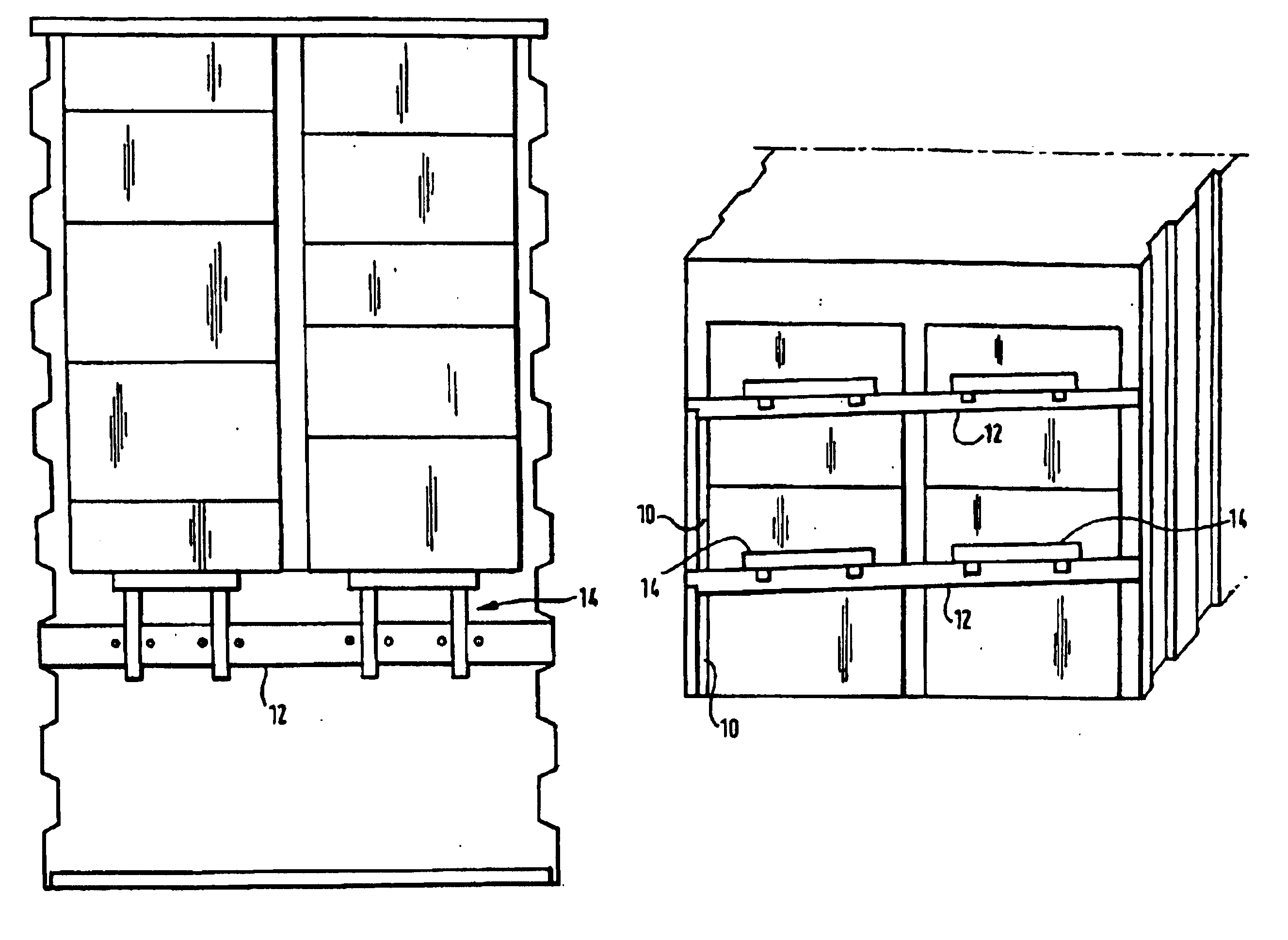
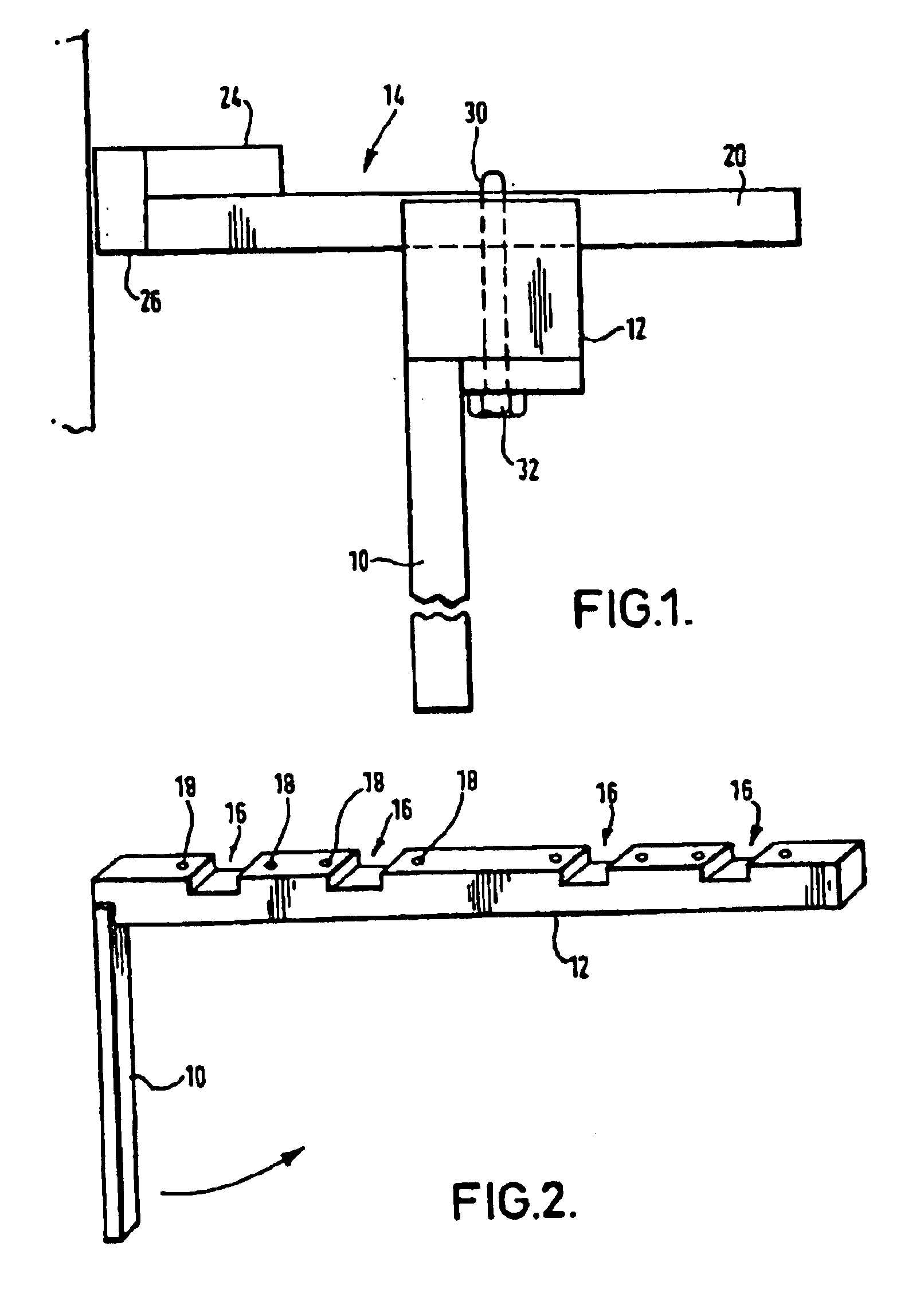
With reference first to FIGS. 1 to 5, a load restraint being a first embodiment will now be described.

The load restraint comprises a support member 10, a transverse member 12 and a load support 14. Each of these components can be formed from timber or fabricated from steel or other metal, as is convenient.

The support member 10 is a straight beam that has a flat lower end surface and a stepped upper end surface. The length of the support member is less than the height of a container into which it is to be used, and less than the height of a load that it is intended to restrain. (In embodiments that are made of wood, the height can easily be lessened by cutting the support member as required.)

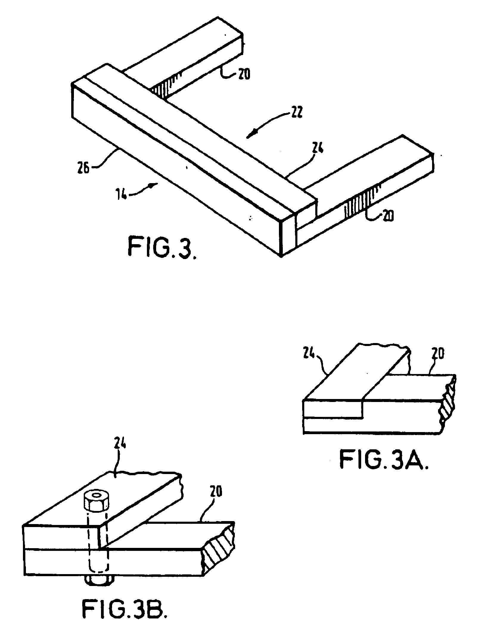
The transverse member 12 is rectangular section a beam of length slightly greater than the width of the container into which the restraint will be installed. An end surface of the transverse member 12 is formed with a step that fits into the corresponding step at the top of the support member 10....

second embodiment

With reference now to FIG. 6, in the invention, the support member 110 and the transverse member 112 are interconnected by a hinge.

In a first modification to the embodiment described above, the support member 10 and the transverse member 12 are interconnected by a flexible fabric or metal hinge 140. The hinge 140 allows the two members to be folded such that they overlie one another; a convenient configuration for storage.

In this embodiment, instead of grooves 16, rectangular slots 116 are formed through the transverse member 112. Bolt holes 118 are formed through the transverse member 112 to intersect with each of the slots.

To install a load restraint of this embodiment, the legs 120 of the load support 114 are inserted through the slots 116 in the transverse member before the support member 110 and the transverse member 112 are installed in the container. After installation, the load restraint 114 is pushed against the load. The installer then inserts a drill into the bolt bole 11...


PUM


Abstract

A load restraint for use in a container is disclosed. The road restraint comprises a support to locate and extend generally vertically within a first locating formation (such as a corrugation in a wall) within a container. A transverse member extends from the support member across the container to engage with a second locating formation (such as another corrugation). A load engaging member is secured to the transverse member to extend from the transverse member to engage a load within the container. The load engaging member is adjustable in position with respect to the transverse member whereby it can contact a load spaced from the transverse member over a range of distances.

Description

BACKGROUND OF INVENTIONThis invention relates to load restraints, and particularly to load restraints for fitting into a freight container or a freight-carrying vehicle.For convenience, in this description, references to a “container” include the load space of a freight-carrying vehicle, unless the context demands otherwise.When freight is packed into a container in many cases, the container is not completely filled. This may be because there is simply insufficient load available to fill the container, or it may be because the density of the load is such that a weight limit is reached before the container is filled. Shippers have a major problem for part loaded containers were there is substantial scope for movement of the product due to transit forces if the cargo is allowed to move longitudinally into free space within the container. Therefore, it is essential that the load be restrained to stop it moving within the container, since this could cause damage to the load or to the co...

Claims


Application Information

Patent Timeline
IPC IPC(8): B60P7/15B60P7/06
CPCB60P7/15
Inventor MOORE, ANTHONY
Owner MOORE ANTHONY
Why Eureka
Try Eureka