Sclera sensor

a sensor and sensor technology, applied in the field of implantable measuring devices, can solve the problems of inability to achieve defined pressure measurement, inability to measure pressure, disadvantage, etc., and achieve the effect of optimal operative ease of insertability and reliable measurement of intraocular pressur

Inactive Publication Date: 2013-06-13
IMPLANDATA OPTHALMIC PROD GMBH
View PDF8 Cites 21 Cited by
  • Summary
  • Abstract
  • Description
  • Claims
  • Application Information

AI Technical Summary

Benefits of technology

The present invention is an implantable measuring device for measuring the intraocular pressure. The device is designed to provide reliable measurement of pressure while avoiding previous disadvantages. The contact area of the housing is designed to make contact with the ocular sclera without the need for press-on force, and the device can be fixed on the ocular sclera without individualized adjustment. The surface contour of the contact area is designed to achieve a form closure with the ocular sclera of a given patient group. The device minimizes artifacts and boundary effects during pressure measurement. The expansion of the measuring area portion is substantially the same as the pressure-sensing area, and a neutralization area portion is used to further minimize artifacts and boundary effects. These technical effects make the invention more reliable and easier to use for measuring intraocular pressure.

Problems solved by technology

Disadvantageously, the known measuring device provides that during the fixation of the same on the ocular sclera, while using the acrylic plate as an abutment, the fluid-filled envelope, containing the pressure sensor in oil or gel and lacking in dimensional stability, is pressed against the ocular sclera with the aid of the acrylic plate applying a press-on force that depends on the concrete fixation and is therefore variable.
A pressure measurement is thus, disadvantageously, only possible after carrying out complex two-point or multiple-point calibrations.
Correspondingly, if at all, any defined pressure measurement can only be achieved at a disadvantage following a corresponding complex calibration of the measured values.
In addition, the apparatus that must be implanted for the measurement of the intraocular pressure on the ocular sclera is disadvantageously complex by comparison.

Method used


Image

  • Sclera sensor
  • Sclera sensor
  • Sclera sensor

Examples


Embodiment Construction

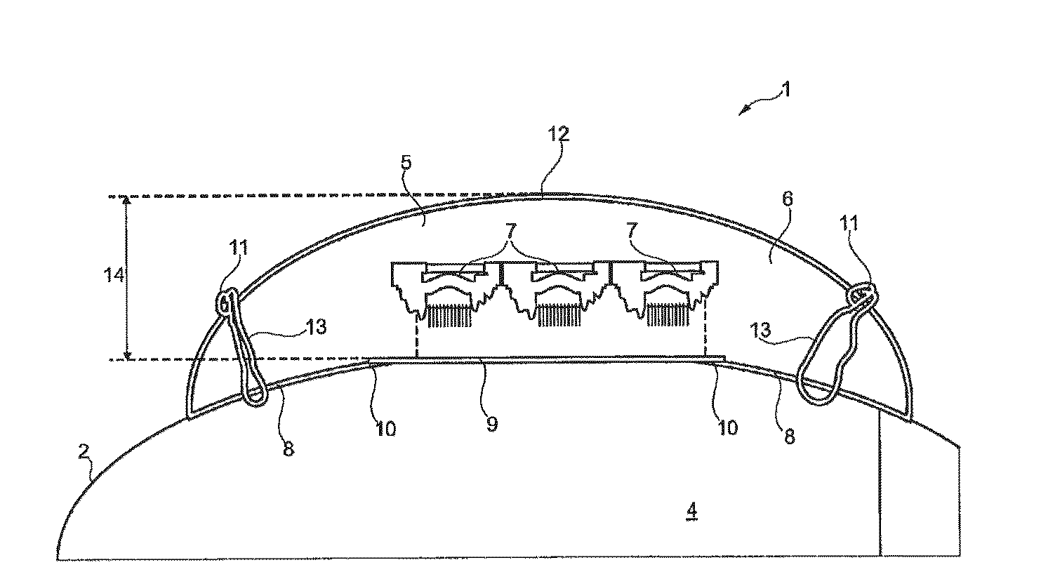
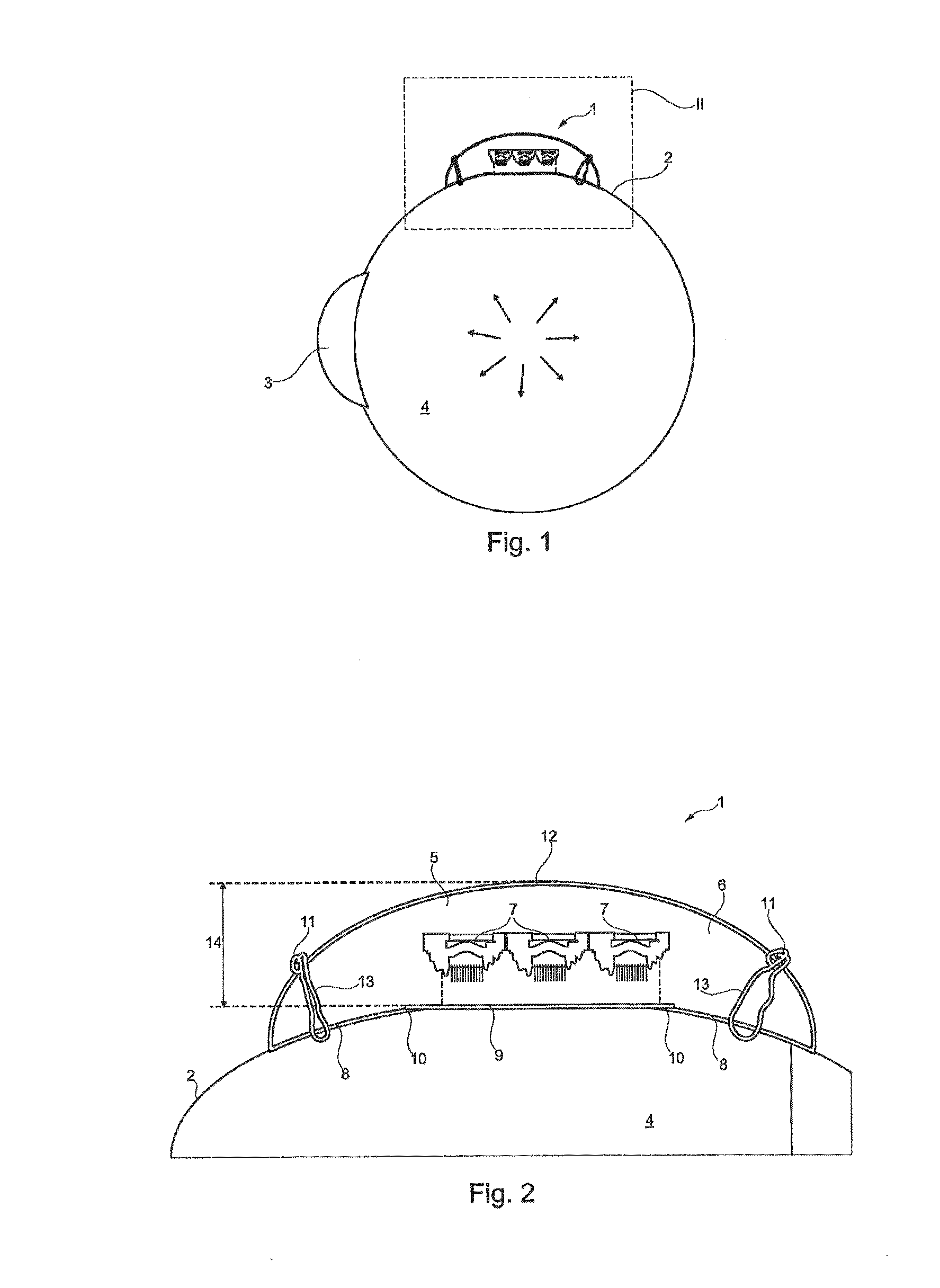
[0032]FIG. 1 is a schematic representation of an implantable measuring device 1 that is fixed laterally on an ocular sclera 2 in the vicinity of the pars plana or behind the pars plana. The figure further shows by way of a schematic representation the cornea 3 of the ball of the eye 4. The intraocular pressure that is prevalent inside the ocular sclera 2 is schematically symbolized by arrows.

[0033]FIG. 2 shows an enlargement of a cut-out of the region specified as II in FIG. 1 for a more detailed explanation of the setup of the implanted measuring device 1. As can be seen in FIG. 2, the implantable measuring device is made up essentially of an ASIC 5 that is embedded in a housing 6. The housing 6 is made, for example, of silicone rubber or another biocompatible rubber-elastic material.

[0034]The ASIC 5 is known in the art. The setup of the same is described, for example, in DE 10 2004 056 757 A1. In particular, the ASIC 5 as depicted in FIG. 2 includes pressure membrane 7 that conver...


PUM


Abstract

The invention relates to an implantable measuring device (1) for measuring the intraocular pressure at an ocular sclera (2), having pressure sensor means (5, 7) embedded in a pressure-transmitting housing (6) for biocompatible contacting of the ocular sclera (2), having at least one, preferably substantially flat, pressure sensor area (7) that allows for a reliable measurement of the intraocular pressure and is operatively easy to insert, in as much as possible, while avoiding the disadvantages of the prior art, wherein it is proposed that the housing (6) is configured with dimensionally stable elasticity.

Description

CROSS REFERENCE TO RELATED APPLICATIONS[0001]This application is the National Phase Application under 35 USC §371 of International Application No. PCT / EP2011 / 064021, filed Aug. 15, 2011, which claims priority to German Patent Application 10 2010 035 294.2, filed Aug. 25, 2010.BACKGROUND[0002]A. Technical Field[0003]The present invention relates to an implantable measuring device for measuring the intraocular pressure at an ocular sclera, having pressure sensor means embedded in a pressure-transmitting housing for biocompatible contacting of the ocular sclera, having at least one, preferably substantially flat, pressure sensor area.[0004]B. Background of the Invention[0005]A measuring device of this type is known in the art from DE 10 2004 056 757 A1. The measuring device allows for measuring the intraocular pressure from an easily accessible location on the eye, in fact extrasclerally, meaning via placement of the device against the ocular sclera. In contrast to intraocular measurin...

Claims


Application Information

Patent Timeline
Patent Type & Authority Applications(United States)
IPC IPC(8): A61B3/16
CPCA61B3/16A61B5/6821A61B5/076
Inventor OSTERMEIER, MAXMEYER, STEFAN
Owner IMPLANDATA OPTHALMIC PROD GMBH
Why Eureka
Try Eureka