
Reactor Components

a technology of reactor components and components, applied in the direction of lighting and heating apparatus, thermal non-catalytic cracking, organic chemistry, etc., can solve the problems of short residence time, increase pressure drop, and reduce the length to diameter ratio of the reactor, so as to enhance the reactor and its operation, increase the temperature, and double the overall heat transfer coefficient

Active Publication Date: 2013-06-13
EXXONMOBIL CHEM PAT INC
View PDF1 Cites 4 Cited by
  • Summary
  • Abstract
  • Description
  • Claims
  • Application Information

AI Technical Summary

Benefits of technology

The patent text discusses a method for improving the performance of regenerative pyrolysis reactors by adjusting heat transfer rates to enhance reactor efficiency. The text explains that heat transfer within the reactor involves convective heat transfer and radiative heat transfer, and that radiative heat transfer is significant at temperatures above 700°C. By adjusting the heat transfer rate, the reactor can achieve faster quenching and shorter residence times, leading to increased reactor efficiency. The text also suggests that the heat transfer mechanism can be utilized to vary the surface area in different zones of the reactor based on the temperature profile and heat transfer mechanism, which can improve flow velocity and decrease pressure drop. Overall, the patent text provides a technical solution for optimizing the performance of regenerative pyrolysis reactors.

Problems solved by technology

Operation of high severity hydrocarbon cracking processes and regenerative pyrolysis reactors involves various competing operational and engineering challenges.
While the high temperatures enhance selectivity to C2 unsaturates, the rapid kinetics of high temperature operation mandate short residence times (e.g., milliseconds).
As a result, high flow velocities of the streams through the reactor or use of shorter reactors are needed to provide these short residence times. Unfortunately, the high flow velocities increase pressure drop, which is yet another challenge for the operation of these reactors.
However, shortening the reactor bed while maintaining high productivity (e.g., volumetric flow rate) results in lowering the length to diameter ratio for the reactor, causing significant flow distribution challenges.
In addition, conventional techniques fail to adequately address the heat transfer rate within the reactor.
Thus, conventional attempts to enhance reactor efficiency by increasing wetted area also result in increased pressure drop.

Method used


Image

  • Reactor Components
  • Reactor Components
  • Reactor Components

Examples


Embodiment Construction

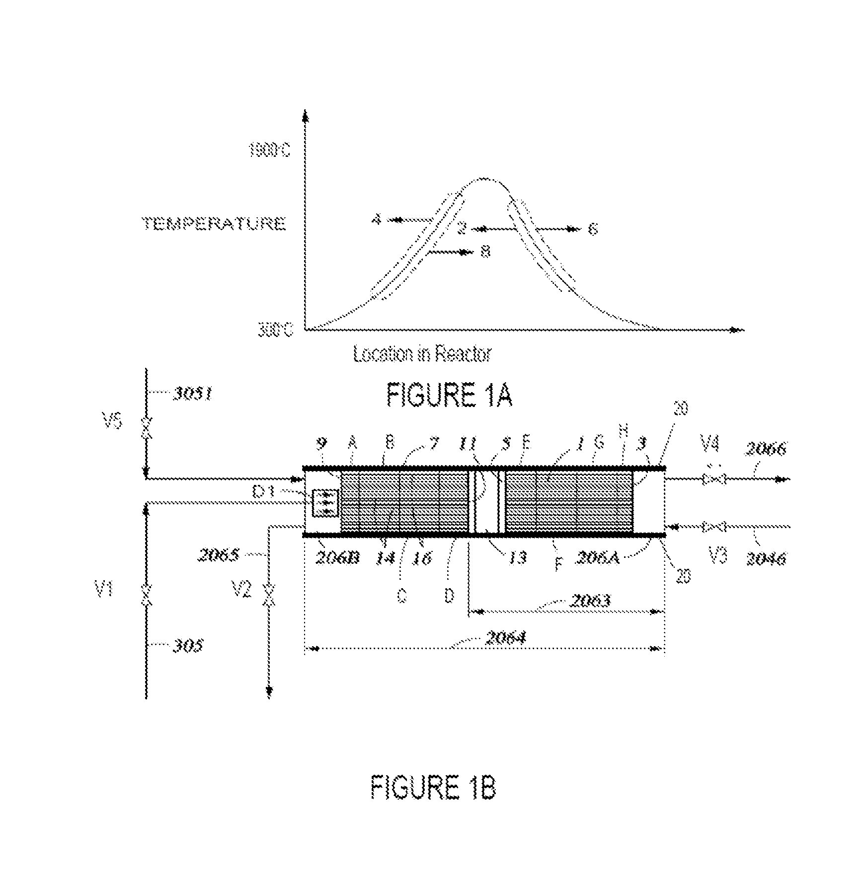
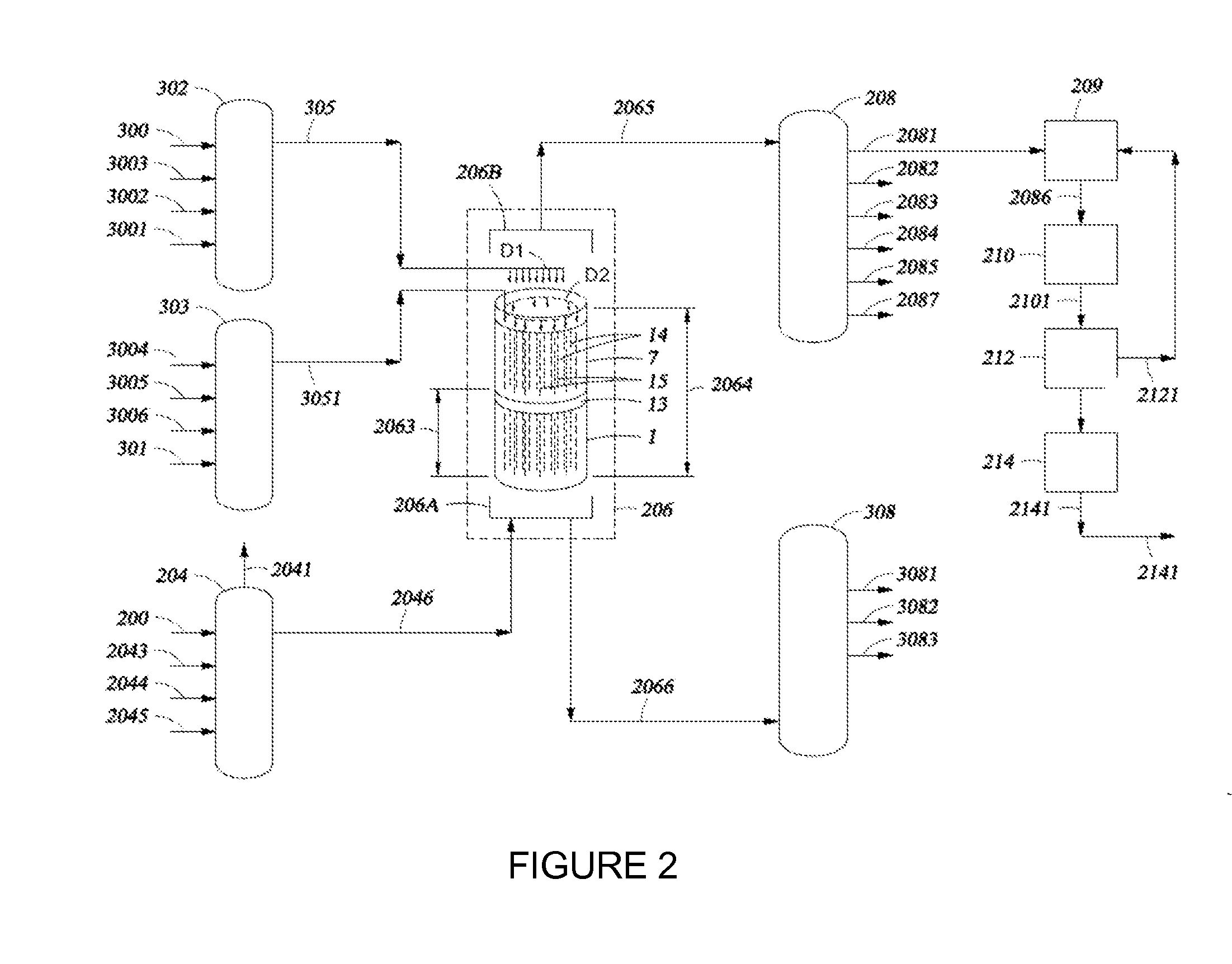
[0022]The present disclosure is based in part on the observation that reactor components, such as insulation and process flow components are utilized in different zones within a reactor, e.g., those described in U.S. Pat. No. 7,943,808 and U.S. Patent Pub. App. Nos. 2010 / 0290978 and 2010 / 0292523. The process flow components may include components that manage the flow of process fluids through the internal zones within the reactor and store and release heat to the process fluids, while the insulation components may include components that inhibit the heat transfer from the interior of the reactor to locations external to the reactor, which may also inhibit the flow of process fluids to locations external to the reactor. The reactor components are sensitive to (a) environmental operating conditions; (b) temperature operating conditions; and / or (c) heat transfer properties based on the location within the reactor. In the reactor, heat transfer concerns the exchange of thermal energy fr...


PUM


Abstract

The present disclosure relates to reactor components and their use, e.g., in regenerative reactors. A process and apparatus for utilizing different wetted areas along the flow path of a fluid in a pyrolysis reactor, e.g., a thermally regenerating reactor, such as a regenerative, reverse-flow reactor, is described.

Description

PRIORITY[0001]The present application claims priority to U.S. Ser. No. 61 / 568,394, filed on Dec. 8, 2011, entitled, “Reactor Components” the entire disclosures of which are hereby incorporated by reference herein.FIELD OF THE INVENTION[0002]The present disclosure relates to reactor components and their use in reactors. The present disclosure encompasses advanced materials, methods, and apparatus useful in regenerative pyrolysis reactors, such as may be used for pyrolyzing or cracking hydrocarbons. In one non-limiting example, the present disclosure relates to advanced use of wetted areas and associated materials, apparatus, and methods suitable for use in cracking hydrocarbon feeds in a high-severity pyrolysis reactor.BACKGROUND OF THE INVENTION[0003]Regenerative pyrolysis reactors may be utilized in pyrolyzing or cracking hydrocarbons. Regenerative reactor cycles are either symmetric (same chemistry or reaction in both directions) or asymmetric (chemistry or reaction changes with s...

Claims


Application Information

Patent Timeline
IPC IPC(8): C07C4/04
CPCB01J2219/00121B01J8/0442B01J2219/0004B01J2219/00155B01J2219/1943B01J2208/0053B01J8/0438B01J2219/00117C10G9/18B01J2219/185B01J2208/00327B01J2219/1923B01J2219/1947C07C4/04B01J19/02F23L15/02B01J4/004B01J2208/00309B01J2219/00159C10G9/26B01J8/0453B01J2208/00911B01J2219/194B01J2219/182B01J2219/0281B01J2208/00495B01J19/2485B01J8/0457B01J2208/00106Y02E20/34B01J8/0423B01J2219/00139
Inventor KEUSENKOTHEN, PAUL F.HERSHKOWITZ, FRANKMOHR, GARY D.CHUN, CHANGMINFREDERICK, JEFFREY W.
Owner EXXONMOBIL CHEM PAT INC
Learn More