Imaging method and apparatus
a technology of image acquisition and method, applied in the field of image acquisition apparatus, can solve the problems of high calculation cost, inability to provide real-time property of image acquisition, and out of focus
- Summary
- Abstract
- Description
- Claims
- Application Information
AI Technical Summary
Benefits of technology
Problems solved by technology
Method used
Image
Examples
second embodiment
2. Second Embodiment
[0085]The second embodiment relates to a method for performing image processing such as noise cancellation from the focused image, by using the deconvolution image or the sweep image generated in the first embodiment. Image processing to be described below is implemented by the image processor 117 of the imaging apparatus 10 according to the first embodiment of the present invention.
[0086]FIG. 4 is a diagram illustrating an example of the structure of the image processor 117 for performing noise cancellation by using a HPF.
[0087]The image processor 117 detects a focused region from two images and averages pixel values of corresponding pixels, respectively, thereby performing noise cancellation.
[0088]Hereinafter, noise cancellation performed by the image processor 117 will be described in detail with reference to FIG. 4.
[0089]As shown in FIG. 4, upon input of a focused image P1 and a deconvolution image P2, the input focused image P1 and deconvolution image P2 pas...
third embodiment
3. Third Embodiment
[0105]The third embodiment relates to a method for separately performing image processing suitable for each region in the focused region and the non-focused region of the focused image by using a determination result for the focused region F in the second embodiment. Image processing described below is implemented by the image processor 117 of the imaging apparatus 10 according to the first embodiment.
[0106]FIGs. 5 and 6 are diagrams illustrating examples of structures of the image processor 117 for separately performing image processing for the focused region and the non-focused region of the focused image. Hereinafter, image processing performed by the image processor 117 will be described in detail.
[0107]First, an example of image processing shown in FIG. 5 will be described.
[0108]An image input unit 151 outputs a pixel value v of a pixel sequentially selected from pixels forming a focused image to a first image processor 153 and a second image processor 155.
[0...
fourth embodiment
4. Fourth Embodiment
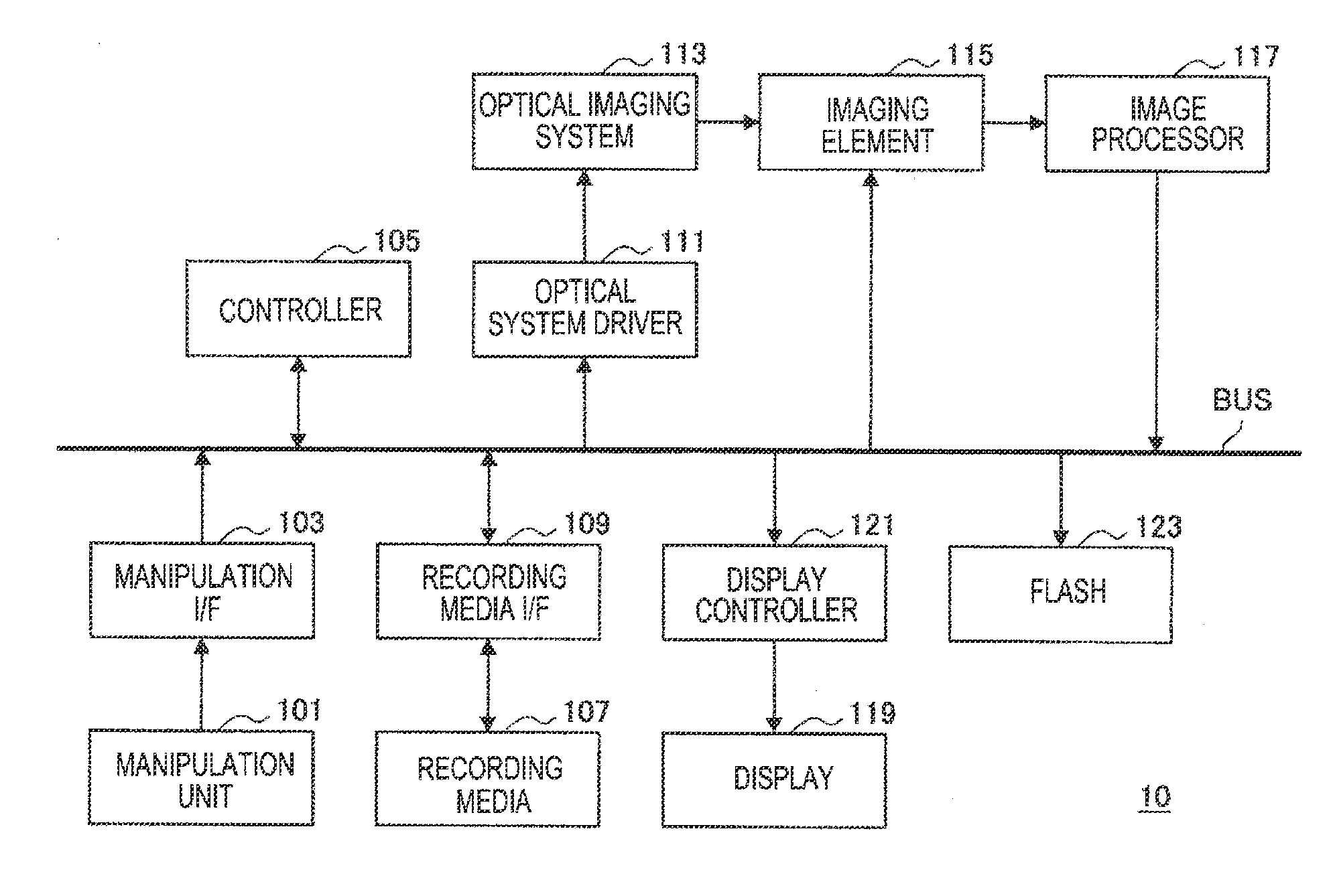
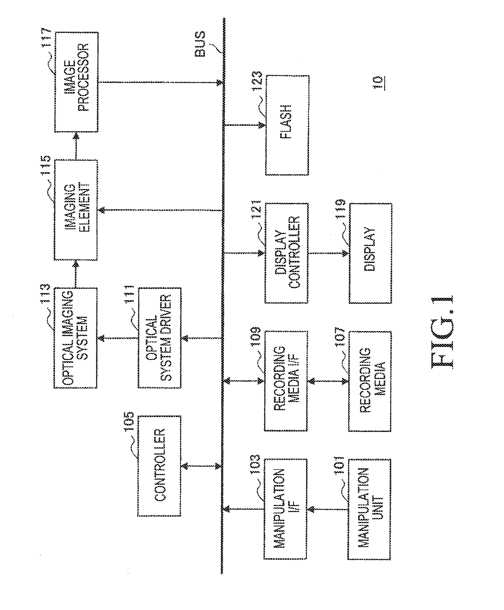
[0127]The fourth embodiment relates to a method for allowing a user to select a desired image from the deconvolution image and the focused image according to the first embodiment. Image processing described below is implemented by each part of the imaging apparatus 10 according to the first embodiment.
[0128]FIG. 7 is a flowchart illustrating a process of displaying an image selection screen according to the fourth embodiment of the present invention.
[0129]As shown in FIG. 7, once the user half-presses the shutter button of the manipulation unit 101 in step S201, the controller 105 of the imaging apparatus 10 determines a focused position and a driving range of a focus lens in step S203.
[0130]The controller 105 performs control for driving the focus lens within the determined focus lens driving range. The optical system driver 111 initiates driving of the focus lens of the optical imaging system 113 and at the same time, initiates exposure, based on control of the...
PUM
 Abstract
Description
Claims
Application Information
 - R&D
- Intellectual Property
- Life Sciences
- Materials
- Tech Scout
- Unparalleled Data Quality
- Higher Quality Content
- 60% Fewer Hallucinations
Browse by: Latest US Patents, China's latest patents, Technical Efficacy Thesaurus, Application Domain, Technology Topic, Popular Technical Reports.
© 2025 PatSnap. All rights reserved.Legal|Privacy policy|Modern Slavery Act Transparency Statement|Sitemap|About US| Contact US: help@patsnap.com


