
Liquid discharge head and image forming apparatus

a liquid discharge head and image forming technology, applied in printing and other directions, can solve the problems of prone to breakage, discharge defect, insufficient stiffness of the filter, etc., and achieve adequate high compliance, stable liquid discharge performance, and high rigidity

Active Publication Date: 2013-06-13
RICOH KK
View PDF21 Cites 14 Cited by
  • Summary
  • Abstract
  • Description
  • Claims
  • Application Information

AI Technical Summary

Benefits of technology

The present invention relates to a liquid discharge head including a filter plate with a filter part and a damper part that reduces pressure variation in the common liquid chamber. The filter part has higher stiffness than the damper part. The technical effect of this arrangement is that stable liquid discharge performance can be maintained and high productivity can be achieved.

Problems solved by technology

Thus, when some foreign particle gets mixed with the ink, the foreign particle may flow with the ink and get stuck in the nozzle to thereby cause a discharge defect.
However, the above disclosures do not contemplate arranging the filter to have high stiffness and arranging the damper to have high compliance in forming the filter and the damper on the same member.
Thus, when the damper is arranged to have adequately high compliance for achieving desired performance, the stiffness of the filter may be inadequate, and the filter may be prone to breaking.

Method used


Image

  • Liquid discharge head and image forming apparatus
  • Liquid discharge head and image forming apparatus
  • Liquid discharge head and image forming apparatus

Examples


Embodiment Construction

[0036]In the following, embodiments of the present invention are described with reference to the accompanying drawings.

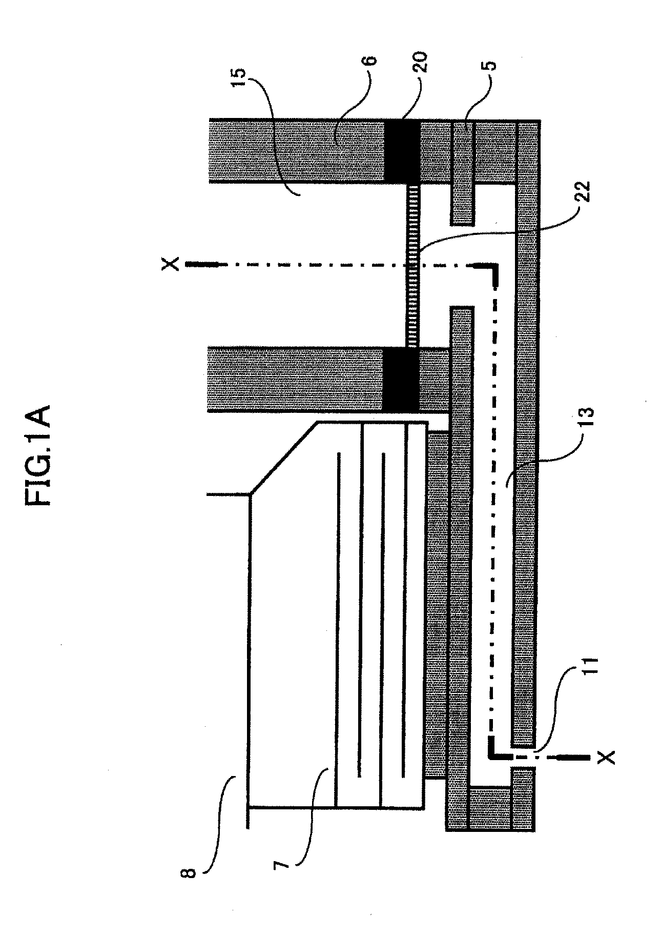
[0037]FIG. 1A is a partial cross-sectional view of a liquid discharge head according to an embodiment of the present invention, and FIG. 1B is a cross-sectional view of section X-X of FIG. 1A.

[0038]The liquid discharge head according to the present embodiment includes plural nozzles 11 that discharge liquid droplets, plural individual liquid chambers (pressurized liquid chambers) 13 that are in communication with the nozzles 11, a common liquid chamber 15 that supplies liquid to the individual liquid chambers 13, and a filter plate 20 that is arranged in a liquid flow path of the common liquid chamber 15. The filter plate 20 include a filter part (internal filter) 22 for filtering the liquid and a damper part 21 for reducing pressure variations in the common liquid chamber 15 formed thereon, and the filter part 22 is arranged to be thicker than the damper part 21. T...


PUM


Abstract

A liquid discharge head includes a nozzle that discharges liquid droplets, a common liquid chamber that supplies liquid to an individual liquid chamber that is in communication with the nozzle, and a filter plate that is arranged in a liquid flow path of the common liquid chamber. The filter plate includes a filter part that filters the liquid and a damper part that reduces a pressure variation in the common liquid chamber, and the filter part is arranged to be thicker than the damper part.

Description

BACKGROUND OF THE INVENTION[0001]1. Field of the Invention[0002]The disclosures herein generally relate to a liquid discharge head and an image forming apparatus including the liquid discharge head.[0003]2. Description of the Related Art[0004]An image forming apparatus of a printer, a facsimile machine, a copier, a plotter, or a multifunction peripheral (MFP) combining one or more of the above functions may be realized by an inkjet recording apparatus, which is a liquid discharge type image forming apparatus that uses a recording head made of a liquid discharge head (liquid droplet discharge head) that discharges liquid droplets, for example.[0005]The liquid discharge type image forming apparatus forms (records or prints) an image by discharging ink droplets from the recording head onto a recording medium (paper sheet, OHP film, etc.) that is being transported. The image forming apparatus may be a serial-type image forming apparatus in which the recording head discharges liquid drop...

Claims


Application Information

Patent Timeline
Patent Type & Authority Applications(United States)
IPC IPC(8): B41J2/20
CPCB41J2/20B41J2/14274B41J2/055B41J2/17563
Inventor KIMURA, YUHASHIMOTO, KENICHIRO
Owner RICOH KK
Learn More