
Power transfer device

a power transfer device and power technology, applied in the direction of belt/chain/gearing, toothed gearing, belt/chain/gearing, etc., can solve the problems of not being able to produce the volume of clean water that is needed for large numbers of people or irrigation or sanitation, and most manually-operated (usually hand-operated) pumping systems that have been tried or used over many years are extremely difficult to operate in a sustained manner

Inactive Publication Date: 2013-06-13
FELTENBERGER BRUCE D
View PDF5 Cites 1 Cited by
  • Summary
  • Abstract
  • Description
  • Claims
  • Application Information

AI Technical Summary

Benefits of technology

The present invention is a device that allows for easy powering of machines and equipment using a pendulum and a linkage system. This device reduces operator fatigue and allows for the use of hand-based power compared to other conventional methods such as lever arms or hand cranks. Overall, the technical effect of this invention is an easily adaptable and efficient way to power machines and equipment.

Problems solved by technology

In under developed countries, there does not appear to be a suitable manually operated pumping system that can lift surface water from rivers, creeks, lakes, ponds or shallow wells a distance up to 25 feet or so from the source water to the pump by a suctioning process, pressurize the water and pump it through filtration or reverse osmosis systems to produce clean drinking water.
Deep water pumping systems such as those our forefathers used for pumping water from wells, may from time to time, on a limited basis, produce small amounts of clean drinking water, but they cannot produce the volume of clean water that is needed for large numbers of people or for irrigation or sanitation.
Most manually-operated (usually hand-operated) pumping systems that have been tried or used over many years are extremely difficult to operate in a sustained manner.
This typically results in extreme operator fatigue and discouragement.
A variety of manually operated pumping systems have been tried over the years; however, none have emerged with the characteristics that are needed to solve water related problems on a wide spread scale.
Additionally, in many areas throughout the world where there is little or no access to electricity or fuels, there is also little or no access to surface water or wells.
Because it was easier to impart the driving force in a rotary fashion to a moving pendulum and because of the unbalanced condition found in a rigid arm pendulum, the operator could last about five times longer before fatigue set in and this resulted in pumping about five times as much water at the same pressure.

Method used


Image

  • Power transfer device
  • Power transfer device
  • Power transfer device

Examples


Embodiment Construction

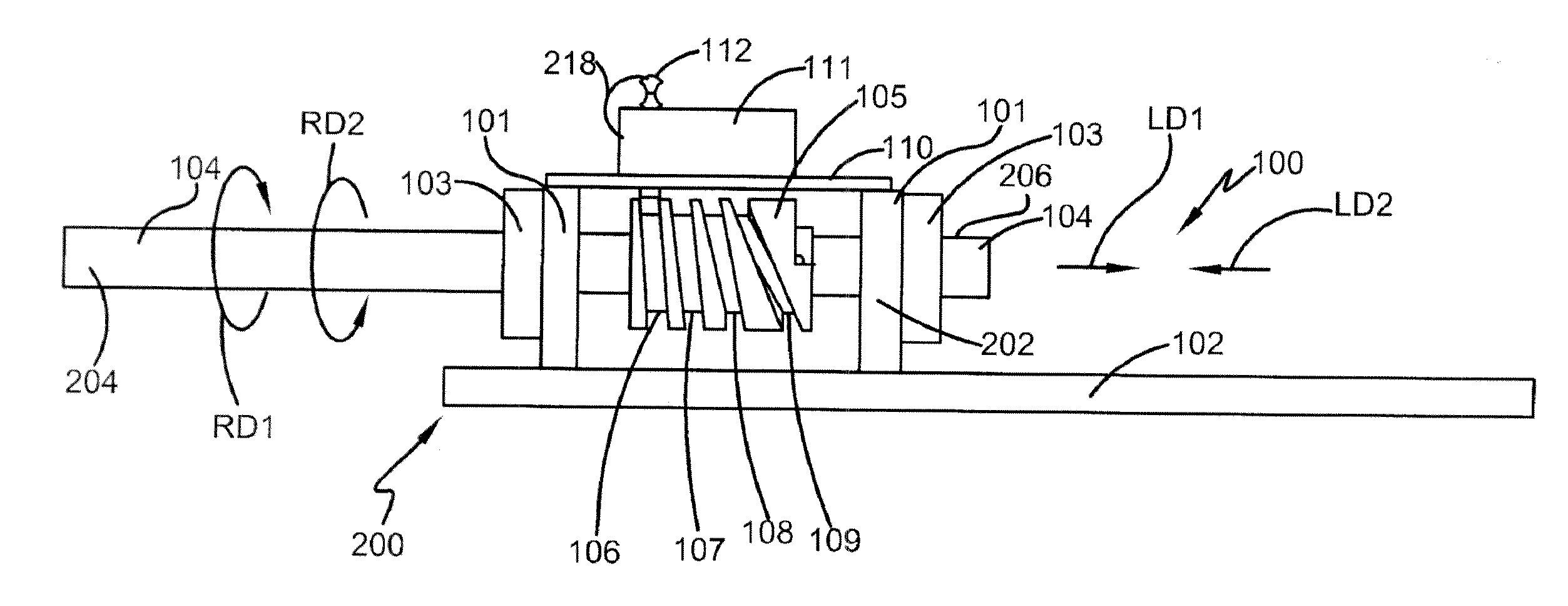
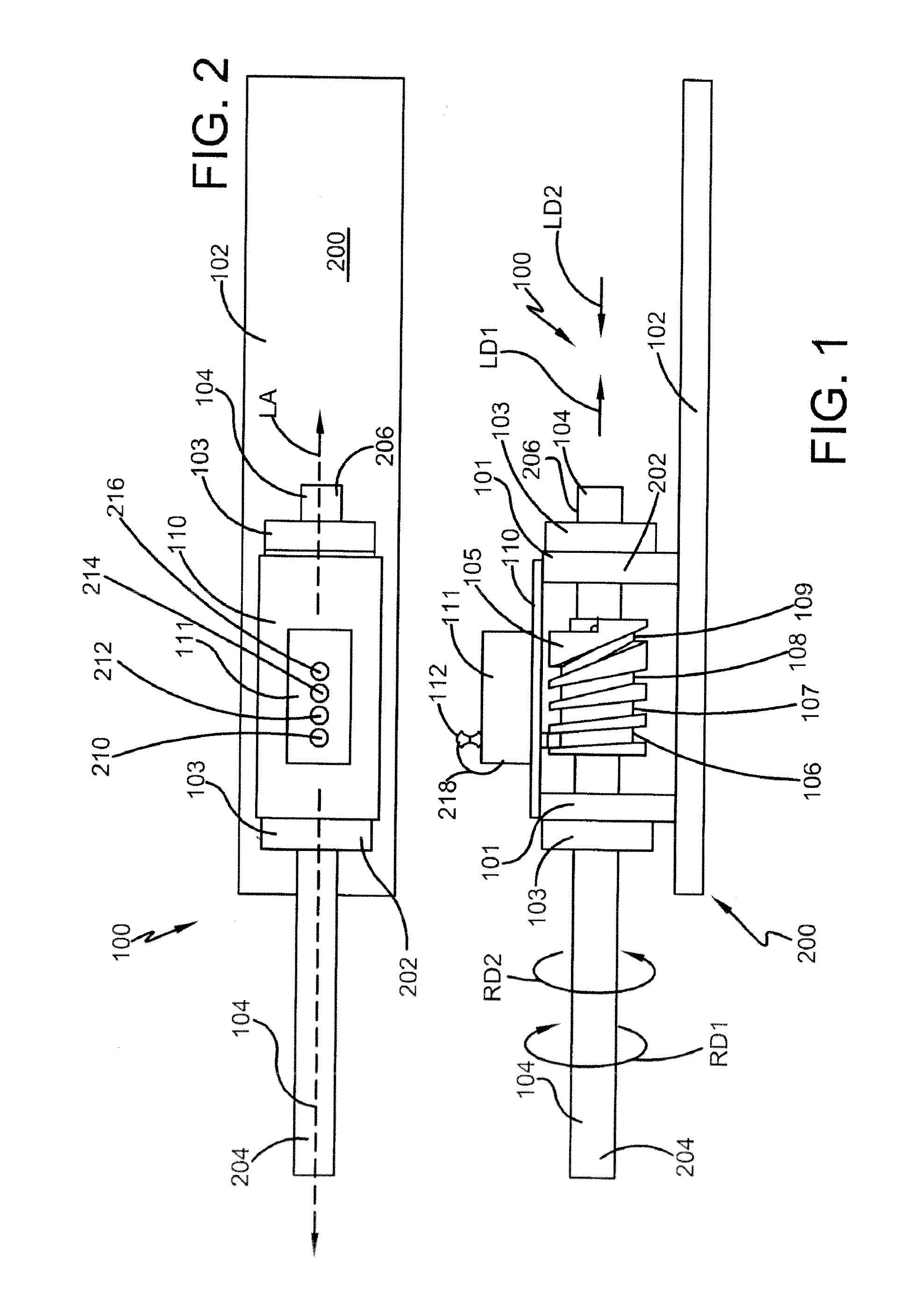
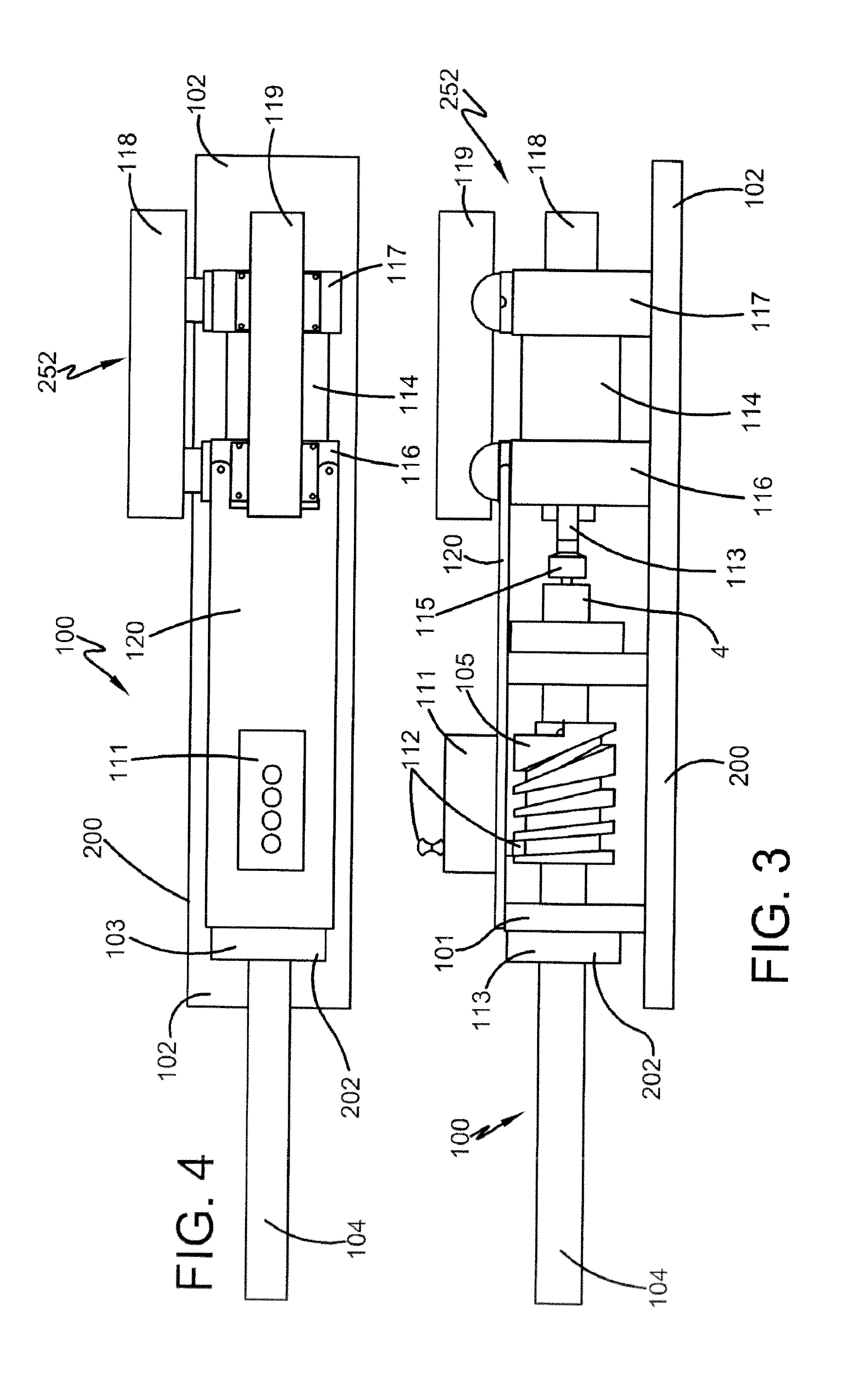
[0038]FIG. 1 and FIG. 2 show a side view and top view respectively of a power transfer device 100 according to one embodiment of this invention. The power transfer device 100 may include a support assembly 200, a bearing assembly 202 supported to the support assembly 200, and an axle 104 that is received within the bearing assembly 202. The support assembly 200 may be of any design chosen with the sound judgment of a person of skill in the art. For the embodiment shown in FIGS. 1-2, the support assembly 200 may include a base plate 102 and a support plate 110. The support assembly 200 may also include a pin holder 111 that is supported to the support plate 110 and used for purposes described below. While the bearing assembly 202 can be of any type and size chosen with the sound judgment of a person of skill in the art, for the embodiment shown it may include two linear bearing blocks 101 rigidly attached to the base plate 102. Linear bearings 103 may be secured to the bearing blocks...


PUM


Abstract

A power transfer device may include a support assembly, a bearing assembly, and an axle that has at least one groove that is angled in a predetermined manner. A guide pin may be received within the groove. Rotation of the axle may then cause a linear input to be received by an output component attached to the end of the axle.

Description

I. BACKGROUND[0001]A. Field of Invention[0002]It is well known that the shortage of clean drinking water and adequate supplies of water for irrigation and sanitation are very big problems worldwide. This is prevalent especially in so called “under developed” countries and also in general for any isolated or remote area where there is limited or no access to electricity or fuels such as gasoline or diesel. In areas such as these, it is too often common to find people drinking contaminated water, going hungry due to the lack of water to irrigate their crops and / or living in deplorable conditions due to the lack of water and pumping capability to provide adequate sanitation.[0003]B. Description of the Related Art[0004]In under developed countries, there does not appear to be a suitable manually operated pumping system that can lift surface water from rivers, creeks, lakes, ponds or shallow wells a distance up to 25 feet or so from the source water to the pump by a suctioning process, p...

Claims


Application Information

Patent Timeline
Patent Type & Authority Applications(United States)
IPC IPC(8): F16H25/12
CPCF16H25/12Y10T74/18664F16H25/186
Inventor FELTENBERGER, BRUCE D.
Owner FELTENBERGER BRUCE D
Learn More