
Disc Space Sizing Devices And Methods Of Using The Same

a technology of disc space and spacing, which is applied in the field of devices for adjusting the spacing between adjacent vertebrae, can solve the problems of increasing trauma, pain, and varying degrees of discomfort and/or pain, and requiring a relatively large delivery cannula or other means,

Active Publication Date: 2013-06-06
SPINAL ELEMENTS INC
View PDF58 Cites 187 Cited by
  • Summary
  • Abstract
  • Description
  • Claims
  • Application Information

AI Technical Summary

Benefits of technology

The present invention provides a spacing device for adjusting the spacing between adjacent vertebral bodies. The device includes a distraction member that is movable between a first and second configuration. When in the first configuration, the device is inserted into the intervertebral disc space and has a first height dimension. When in the second configuration, the device is moved to a larger configuration to adjust the spacing between adjacent vertebral bodies. The device is used by inserting it into the intervertebral disc space and using force to separate the adjacent vertebral bodies. It is then removed from the space. The technical effect of this invention is the ability to adjust the spacing between adjacent vertebral bodies in a minimally invasive way.

Problems solved by technology

Improper spacing between adjacent vertebral bodies can lead to varying degrees of discomfort and / or pain and, if severe enough, may be reason for surgical correction of the spacing.
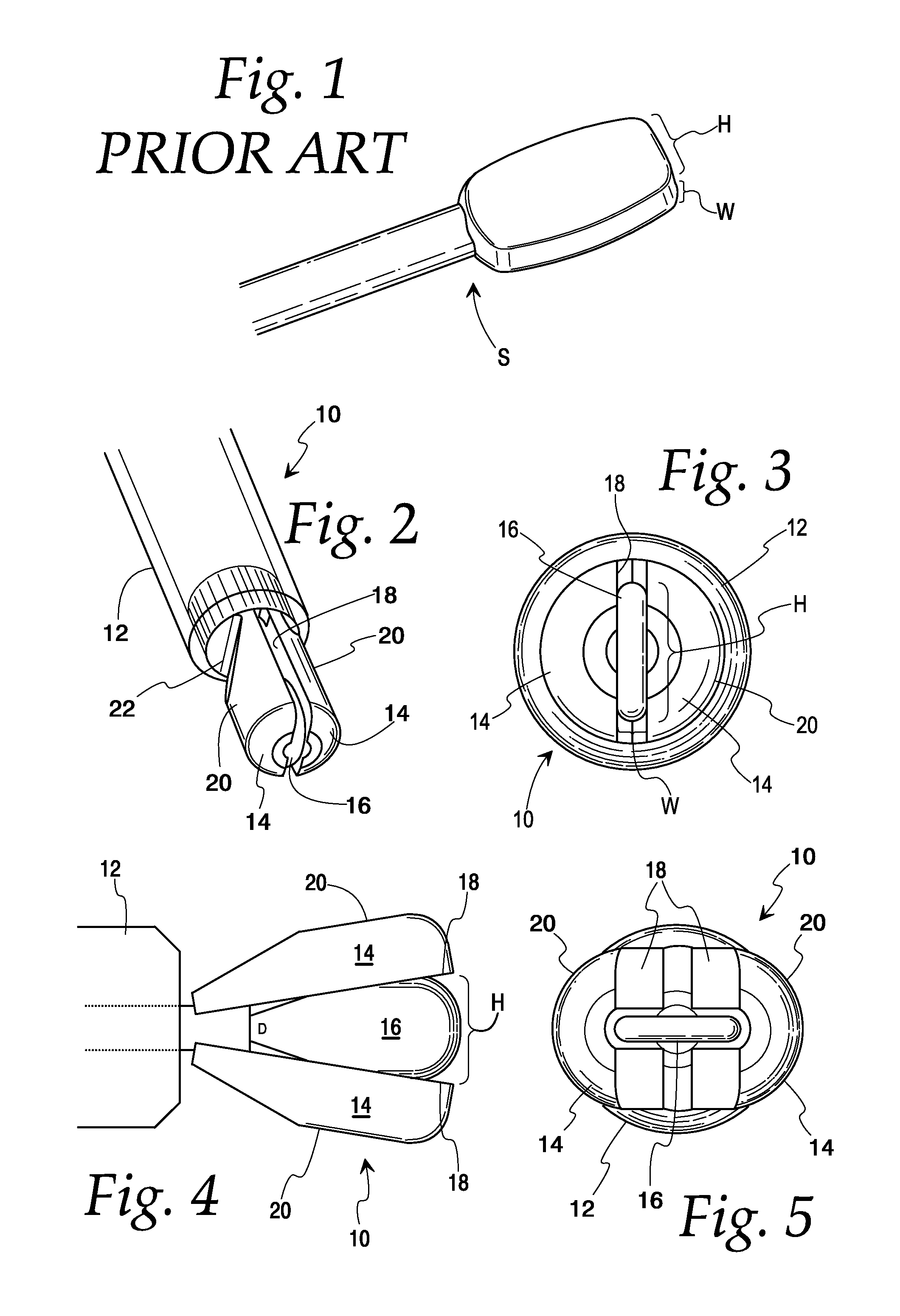
One disadvantage to such an approach is that the means for delivering the distal end of the paddle S to the disc area (e.g., a working cannula) must be large enough to accommodate the height H and the width W. Accordingly, a relatively large delivery cannula or means is required to accommodate the larger-sized paddles.
This can lead to the possibility of greater trauma, loss of blood, and pain, as well as potentially increased surgical and recovery time.
Nerve root retraction is one of the largest potential sources of patient harm in such procedures, and excessive retraction can lead to temporary or even permanent neural dysfunction.
Another disadvantage is that each paddle is appropriate for only one separation amount, so if a particular paddle is initially used and found to result in improper spacing, it must be removed and the process repeated with a paddle having a different height.
The multiple tool exchanges inherent in such an iterative sizing procedure increases the risk of damaging nerve roots or other surrounding structures.

Method used


Image

  • Disc Space Sizing Devices And Methods Of Using The Same
  • Disc Space Sizing Devices And Methods Of Using The Same
  • Disc Space Sizing Devices And Methods Of Using The Same

Examples


Embodiment Construction

[0064]The embodiments disclosed herein are for the purpose of providing the required description of the present subject matter. They are only exemplary, and may be embodied in various forms. Therefore, specific details disclosed herein are not to be interpreted as limiting the subject matter as defined in the accompanying claims.

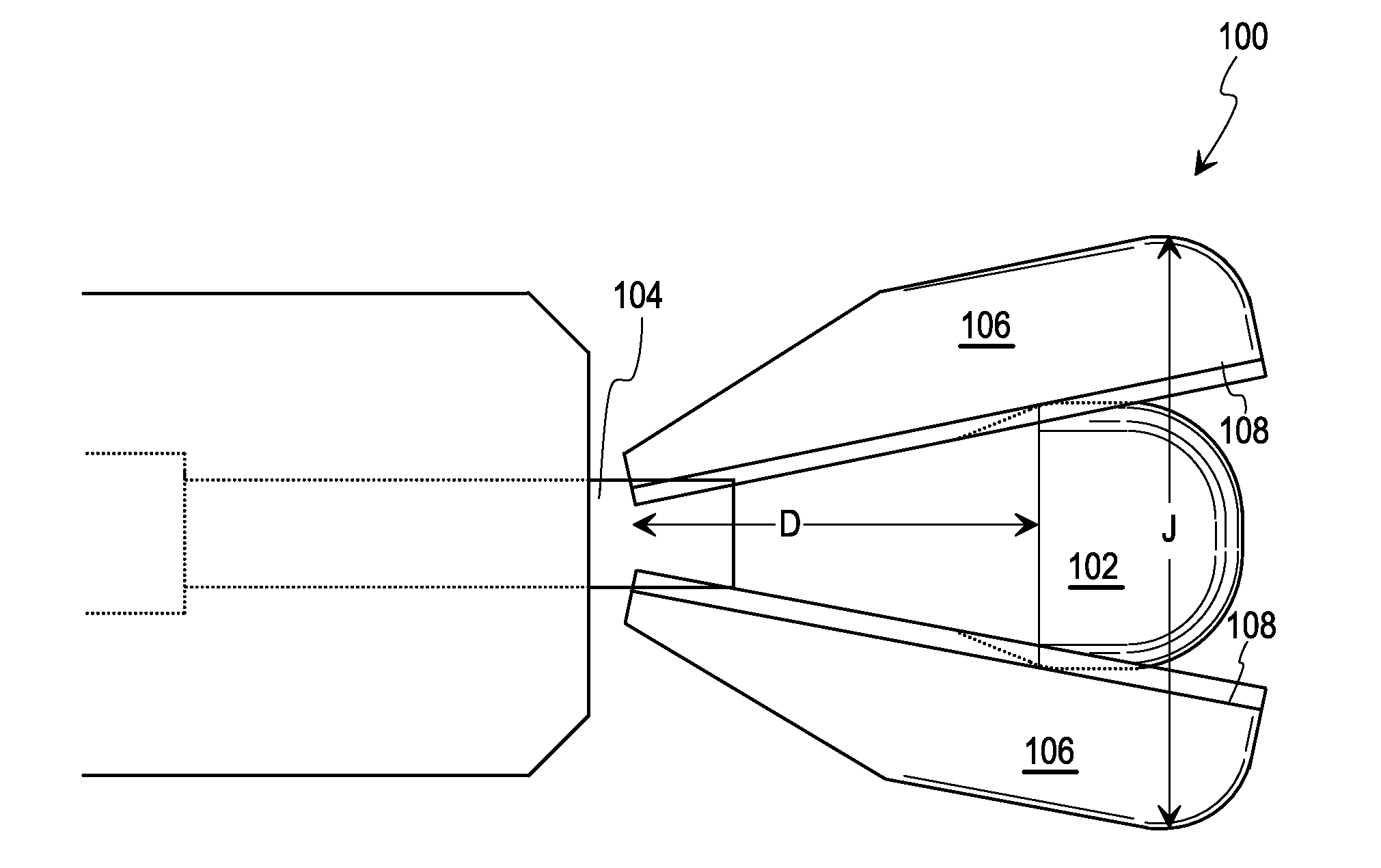
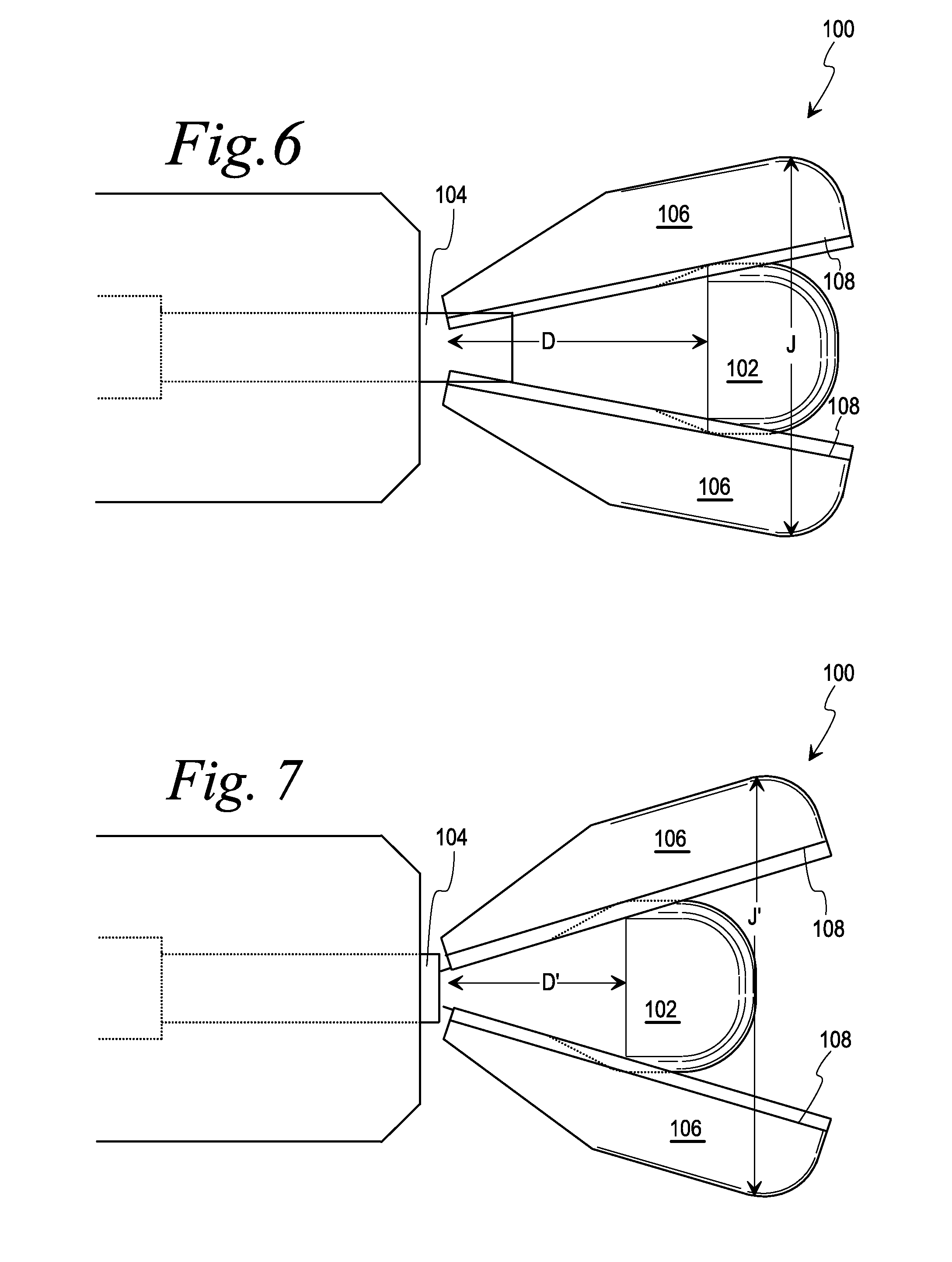
[0065]FIGS. 2-54 show exemplary embodiments of spacing devices according to the present disclosure. The spacing devices described herein are advantageous in that they have a small initial, first, or “collapsed” profile (e.g., in the range of approximately 6-8 mm in width and in height) when entering a target disc space, but are movable (by operation of an actuator) to a different or second configuration having a larger profile (e.g., in the range of approximately 8-15 mm) which is suitable for spacing apart two vertebral bodies in preparation for implantation of an intervertebral body fusion implant or cage. The small initial profile permits the use of a min...


PUM


Abstract

A spacing device is provided for adjusting the spacing between adjacent vertebral bodies. The spacing device has a distal end with at least one distraction member adapted for insertion into an intervertebral disc space and movable between a low profile first configuration and a higher profile second configuration. Also provided is an actuator for moving the distraction member between the first configuration (for delivery of the distal end of the spacing device to a target disc space) and the second configuration (for manipulation of the space between adjacent vertebral bodies).

Description

CROSS-REFERENCE TO RELATED APPLICATIONS[0001]This application claims the benefit of U.S. provisional patent application No. 61 / 349,587, filed May 28, 2010, which is hereby incorporated herein by reference.BACKGROUND[0002]1. Field of the Disclosure[0003]The present subject matter relates to devices for adjusting the spacing between adjacent vertebral bodies.[0004]2. Description of Related Art[0005]The spacing in the disc space between adjacent vertebral bodies may decrease for any of a number of reasons, including traumatic impacts and degenerative diseases. Improper spacing between adjacent vertebral bodies can lead to varying degrees of discomfort and / or pain and, if severe enough, may be reason for surgical correction of the spacing. Surgical correction often involves placement of an inter-body implant to support the vertebrae and restore the disc height to (or close to) its original height. To determine the proper size of the implant to place into the disc space, the current prac...

Claims


Application Information

Patent Timeline
Patent Type & Authority Applications(United States)
IPC IPC(8): A61F2/44
CPCA61B17/025A61B2017/0256A61B2017/2933A61F2002/4658A61B2017/2943A61F2/442A61F2002/30579A61B2017/2941A61F2/4455A61B17/885A61B17/8852
Inventor EMERY, JEFFREY L.HIROTSUKA, MARK YBURLEY, J. BROOK
Owner SPINAL ELEMENTS INC
Learn More