
Method and equipment for detecting rotating stall and compressor

a technology of rotating stall and compressor, which is applied in the direction of mechanical equipment, machines/engines, liquid fuel engines, etc., can solve the problems of reducing the efficiency of compressors, and reducing the efficiency of compressed fluids

Active Publication Date: 2013-06-06
NUOVO PIGNONE TECH SRL
View PDF2 Cites 8 Cited by
  • Summary
  • Abstract
  • Description
  • Claims
  • Application Information

AI Technical Summary

Benefits of technology

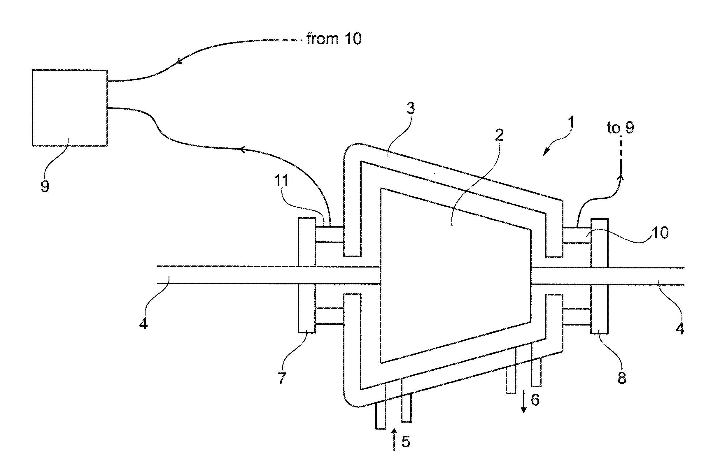
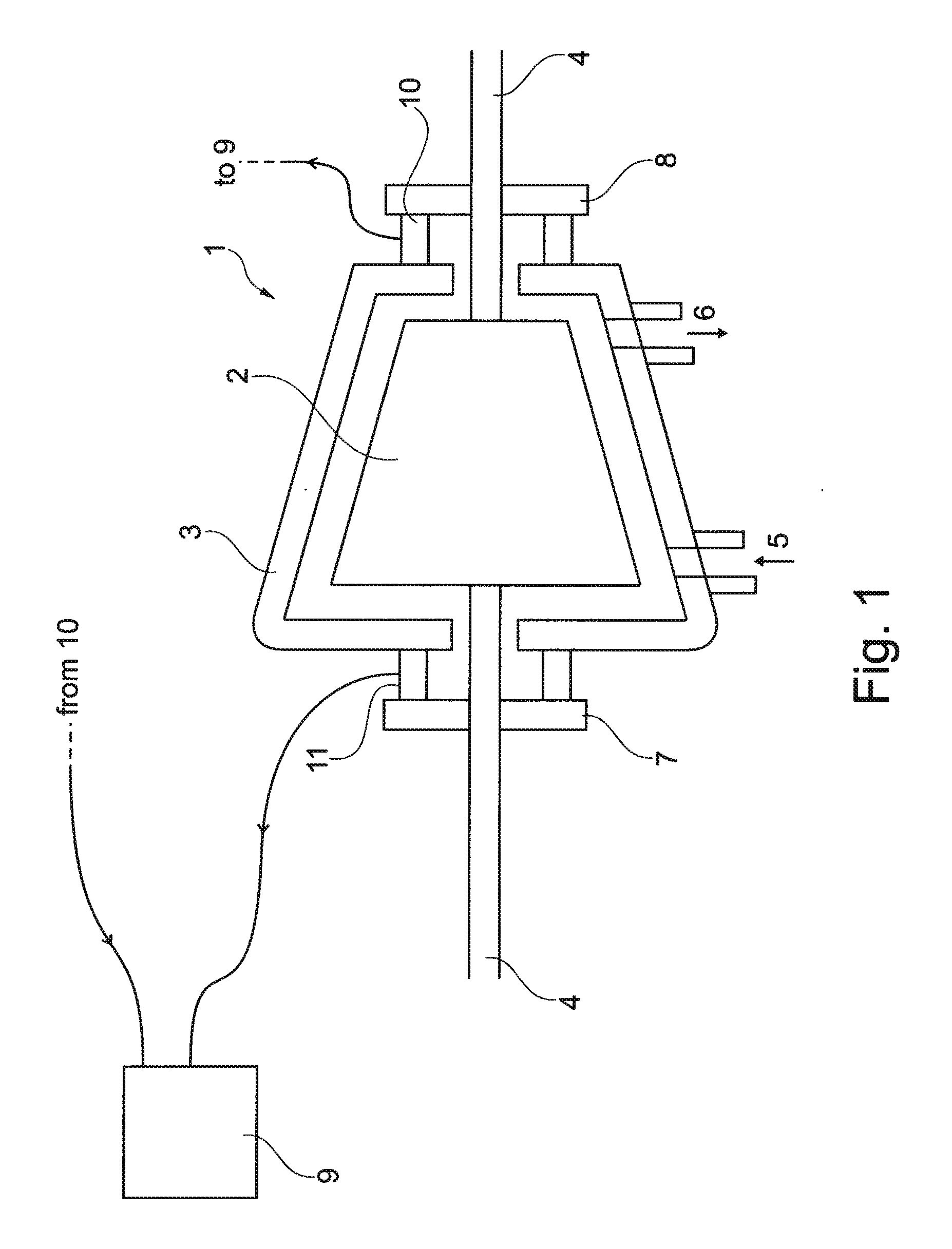
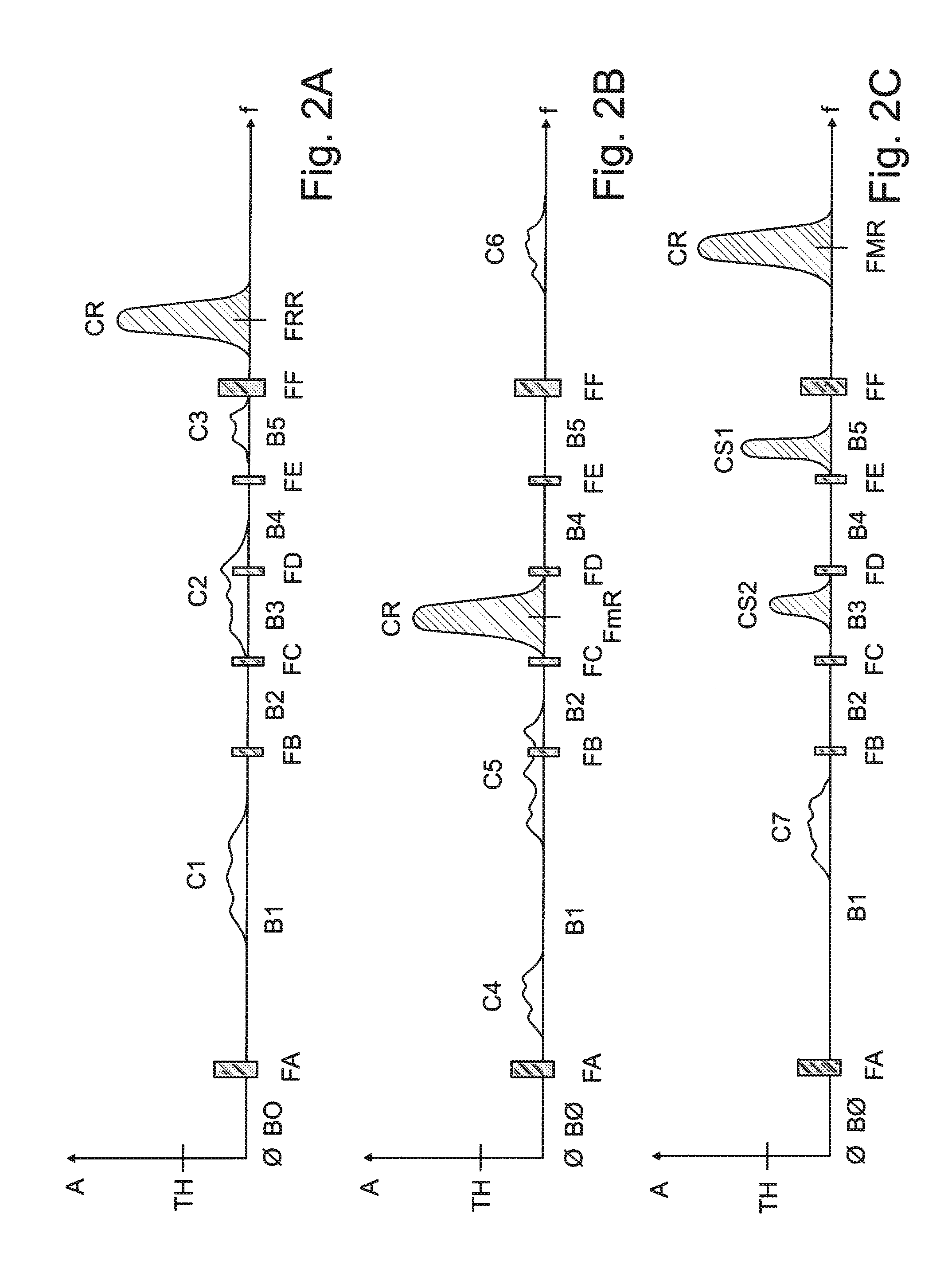
The present invention relates to a method and apparatus for detecting rotating stall in a compressor. The technical effect of this invention is to provide a reliable and accurate way to detect rotating stall, which can help to prevent damage to the compressor and improve operational efficiency. The method involves measuring the radial vibration of the rotor relative to the stator and analyzing the frequency spectrum of the vibration measurement signal. The apparatus includes a sensor and an electronic processing unit that calculates the frequency spectrum, identifies the frequency bandwidths, and determines the maximum magnitude of the spectrum in each bandwidth. The maximum magnitude is then compared to a predetermined value, and if there is a significant difference, a rotating stall condition is considered to be present.

Problems solved by technology

Rotating stall, also known as rotational stall, is a local disruption of airflow within a compressor which continues to provide compressed fluid but with reduced effectiveness.
Local stalls substantially reduce the efficiency of the compressor and increase the structural loads on the aerofoils encountering stall cells in the region affected.
In many cases, however, the compressor aerofoils are critically loaded without capacity to absorb the disturbance to normal airflow such that the original stall cells affect neighboring regions and the stalled region rapidly grows to become a complete compressor stall which is commonly known as surge.
If surge continues and no action is taken to stop it, the rotor blades will be severely damaged and, eventually, the whole compressor will be damaged.

Method used


Image

  • Method and equipment for detecting rotating stall and compressor
  • Method and equipment for detecting rotating stall and compressor
  • Method and equipment for detecting rotating stall and compressor

Examples


Embodiment Construction

[0031]The following description of the exemplary embodiments refers to the accompanying drawings. The same reference numbers in different drawings identify the same or similar elements. The following detailed description does not limit embodiments of the invention. Instead, the scope of embodiments of the invention is defined by the appended claims. The following embodiments are discussed, for simplicity, with regard to the terminology and structure of a centrifugal compressor. However, the embodiments to be discussed next are not limited to this kind of system, but may be applied for example to axial compressors.

[0032]Reference throughout the specification to “one embodiment” or “an embodiment” means that a particular feature, structure, or characteristic described in connection with an embodiment is included in at least one embodiment of the subject matter disclosed. Thus, the appearance of the phrases “in one embodiment” or “in an embodiment” in various places throughout the spec...


PUM


Abstract

A method for detecting rotating stall in a compressor is disclosed herein. The method comprises measuring radial vibration of the rotor relative to the stator and generating a vibration measurement signal, calculating a frequency spectrum of the vibration measurement signal, identifying a plurality of frequency bandwidths of the frequency spectrum, neglecting one first frequency bandwidth of the plurality of frequency bandwidths if the rotation frequency of the rotor falls within the first frequency bandwidth, neglecting at least one second frequency bandwidth of the plurality of frequency bandwidths if the rotation frequency of the rotor falls below the second frequency bandwidth, determining the maximum magnitude of the spectrum in each of the non-neglected frequency bandwidths, and comparing each determined maximum magnitude and a predetermined value. Rotating stall is considered occurring if at least one of the comparisons shows that the corresponding determined maximum magnitude is greater than the predetermined value.

Description

BACKGROUND OF THE INVENTION[0001]Embodiments of the present invention disclosed herein generally relate to a method and apparatus for detecting rotating stall in a compressor, in particular in a centrifugal compressor.[0002]Rotating stall, also known as rotational stall, is a local disruption of airflow within a compressor which continues to provide compressed fluid but with reduced effectiveness.[0003]Rotating stall arises when a small proportion of aerofoils experience aerofoil stall, disrupting the local airflow without destabilizing the compressor. The stalled aerofoils create pockets of relatively stagnant fluid (referred to as stall cells) which, rather than moving in the flow direction, rotate around the circumference of the compressor. The stall cells rotate with the rotor blades, but at a lower speed, affecting subsequent aerofoils around the rotor as each encounters the stall cell.[0004]A rotating stall may be momentary, resulting from an external disturbance, or may be st...

Claims


Application Information

Patent Timeline
IPC IPC(8): F04D29/66
CPCF04D27/001F04D29/661F05D2270/101
Inventor ROSSI, DAVIDGALEOTTI, DANIELE
Owner NUOVO PIGNONE TECH SRL
Learn More