Earmuff and headset with the same

Active Publication Date: 2013-06-06
GIGA BYTE TECH CO LTD
View PDF3 Cites 11 Cited by
  • Summary
  • Abstract
  • Description
  • Claims
  • Application Information

AI Technical Summary

Benefits of technology

The present invention provides an earmuff and headset designed to improve sound quality and comfortableness. The earmuff has a through hole to allow air flow for heat dissipation via convection, and a shelter that allows the wearer to regulate the circumference openness of the through hole easily. The design also solves the problem of the enclosed structure of the conventional earmuff and produces a better sound quality. Overall, the invention offers more integrated functions and better sound quality, while also addressing the requirements of both sound quality and ventilation at the same time.

Problems solved by technology

However, the design of the in-ear earphone is often limited and simplified, so that the sound quality thereof is not satisfactory.
Because the earmuff surrounds the ear completely, discomfort resulted from for example stuffiness or weight will arise after the use of the circumaural headset for a long period of time.
So the wearer tends to decrease his / her time of the use of such headset.
In addition, the problem of the stuffiness caused by a long-term use further makes the wearer sweat and heat generated by the working electronic components is gradually accumulated during this period.
The moisture and the accumulated heat may reduce the lifetime of the earphone.

Method used


Image

  • Earmuff and headset with the same
  • Earmuff and headset with the same
  • Earmuff and headset with the same

Examples


first embodiment

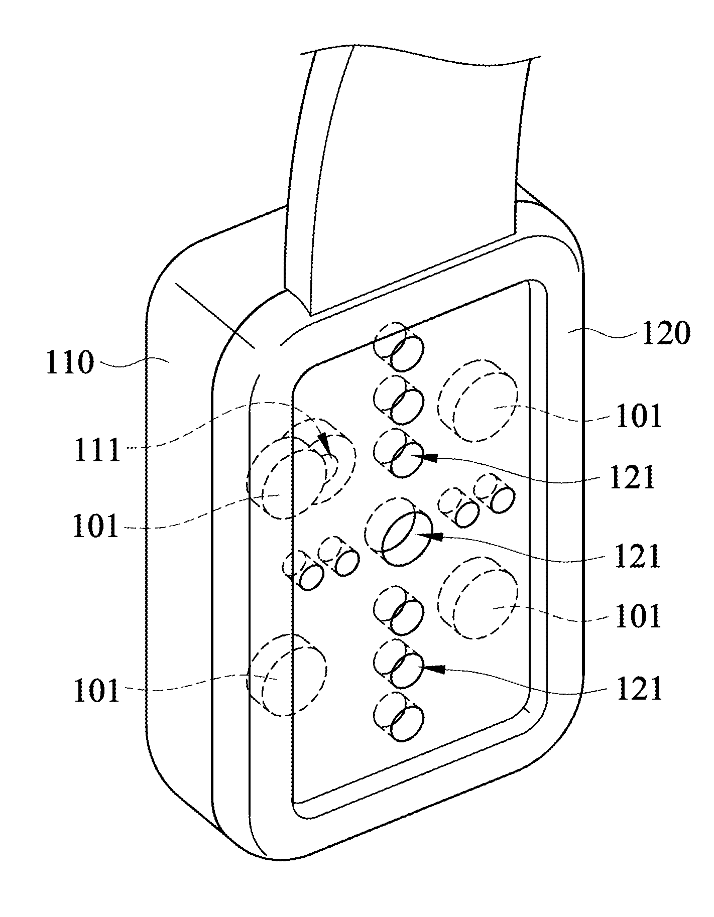
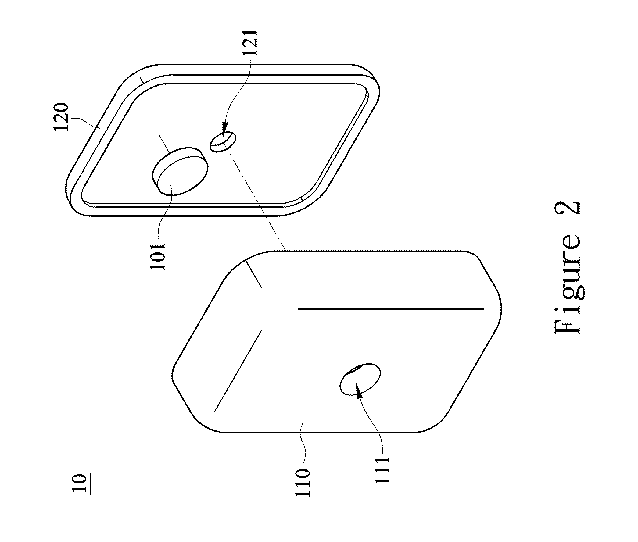
[0040]It is to be noted that the number (one) of each of the first through hole 111 and the second through hole 121 in the first embodiment is only illustrative rather than limitative. The number of more than one is possible in the present invention and it may be determined depending on one's need.

[0041]In practice, one single first through hole 111 together with one single second through hole 121 are sufficient for the effect of heat dissipation and ventilation.

[0042]However, preferably, a more appropriate number of the first through holes 111 and four second through holes 121 is four respectively. Under this condition, more air flow paths are formed between the first case 110 and the second case 120 via the arrangement of the first through holes 111 and the second through holes 121, thereby facilitating the heat transfer rate of the earmuff 10.

[0043]FIG. 3A illustrates a cross-sectional view of an earmuff of a second embodiment according to the present invention. The structure of ...

third embodiment

[0044]FIG. 3B illustrates a cross-sectional view of an earmuff of a third embodiment according to the present invention. The structure of the earmuff of the present embodiment is similar to the aforesaid embodiments except the circumference of the first through hole 111 is relatively smaller than that of the second through hole 121.

[0045]Although not limited to those disclosed in the embodiments of the present invention, the circumference of the first through hole 111 and the second through hole 121 may be properly designed and arranged. Because if the circumferences thereof are too small, the effect of heat dissipation and ventilation caused by air flow will not be quite apparent; on the contrary, if the circumferences thereof are too large, the sound quality will be influenced unfavorably by the intrusive external noise.

[0046]Therefore, preferably, the second through hole 121 nearer to the ear has a larger circumference to afford the wearer comfortableness due to better heat dissi...

fourth embodiment

[0048]FIG. 3C illustrates a cross-sectional view of an earmuff of a fourth embodiment according to the present invention. The structure of the earmuff of the present embodiment is similar to the aforesaid embodiments except the numbers of the first through holes 111 and the second through holes 121 which are opposed to each other are plural and equal.

[0049]FIG. 3D illustrates a cross-sectional view of an earmuff of a fifth embodiment according to the present invention. The structure of the earmuff of the present embodiment is similar to the fourth embodiment except the circumference of the first through hole 111 is relatively smaller than that of the second through hole 121. It is preferable that the circumference of the first through hole 111 may be equal to or less than that of the second through hole 121 in the present invention.


PUM


Abstract

An earmuff which is adapted to covering a driver includes a first case having a first through hole and a second case having a second through hole. The second case accommodated within the first case to form an inner chamber where the driver is disposed therein. Since air flows between the first case and the second case via the first through hole and the second through hole, a satisfactory ventilation effect can be achieved and thus feeling of being at ease can be furnished.

Description

[0001]This application claims the benefit of the filing date of Taiwan Patent Application No. 100144534, filed on Dec. 2, 2011, in the Taiwan Intellectual Property Office, the disclosure of which is incorporated herein in its entirety by reference.BACKGROUND OF THE INVENTION[0002]1. Field of Invention[0003]The present invention relates to an earmuff and a headset with the same; in particular, relates to an earmuff that possesses a through hole and a headset with the same.[0004]2. Related Art[0005]There are several versions of headsets currently, such as a small-sized in-ear type, an ear hook type, or a circumaural type, to satisfy various user requirements. Generally speaking, the in-ear headset is applied prevalently in the mobile applications that require a small size, lightweight and convenience. However, the design of the in-ear earphone is often limited and simplified, so that the sound quality thereof is not satisfactory.[0006]Among them, the circumaural headset earphone usual...

Claims


Application Information

Patent Timeline
IPC IPC(8): H04R1/10
CPCH04R1/1008
Inventor LIN, YIN YU
Owner GIGA BYTE TECH CO LTD
Why Eureka
Try Eureka