Flexible pouring spout

a flexible, pouring spout technology, applied in the direction of liquid dispensing, special dispensing means, packaging, etc., can solve the problems of fluid contamination of the underlying surface, oil or other liquid contamination, frequent contamination, etc., to achieve rapid fluid flow, easy hanging up for storage, and not drip

Active Publication Date: 2013-06-06
EXPRESS PROD LLC
View PDF11 Cites 8 Cited by
  • Summary
  • Abstract
  • Description
  • Claims
  • Application Information

AI Technical Summary

Benefits of technology

This patent addresses the shortcomings of prior art by providing a flexible pour spout that remains clean, even when used with sticky or oily substances. The spout forms a loop when coupled together, making it easy for storage and preventing fluid from dripping. The spout also has an air inlet valve that prevents fluid lock and bottle collapse, facilitating quick and efficient pouring of fluids. A sealing cap can be added to the spout for further protection.

Problems solved by technology

One difficulty with some prior art funnels or elongated flexible pouring spouts is that they frequently become contaminated, particularly if they are used with some sticky substance such as oil, coolant and the like.
When such spout is not in use, the oily surface of the interior attracts and retains dust and dirt so that the next time the spout or funnel is used, the oil or other liquid becomes contaminated.
Further, when such flexible spouts or funnels are hung up for storage, they tend to drip and cause unsightly stains and contamination of the underlying surface by the fluid.
A further drawback of some of the prior art spouts or funnels is that they are not adapted to fit closely to the mouth of the container from which the fluid is poured, thus spills are frequent when either the spout or container is inadvertently moved, resulting in an inconvenience to the user for having to clean up the spill or a detrimental environmental impact in the case of oils and coolants leaking into the ground.
Yet another drawback of some of the prior art spouts or funnels is that they often become fluid locked as a result of the inability to efficiently draw air into their fluid passageway once said passageway becomes blocked with the fluid, resulting in slow fluid flow through the device.

Method used


Image

  • Flexible pouring spout
  • Flexible pouring spout
  • Flexible pouring spout

Examples


Embodiment Construction

[0033]For the purposes of promoting an understanding of the principles of the invention, reference will now be made to the exemplary embodiments illustrated in the drawings, and specific language will be used to describe the same. It will nevertheless be understood that no limitation of the scope of the invention is thereby intended. Any alterations and further modifications of the inventive features illustrated herein, and any additional applications of the principles of the invention as illustrated herein, which would occur to one skilled in the relevant art and having possession of this disclosure, are to be considered within the scope of the invention.

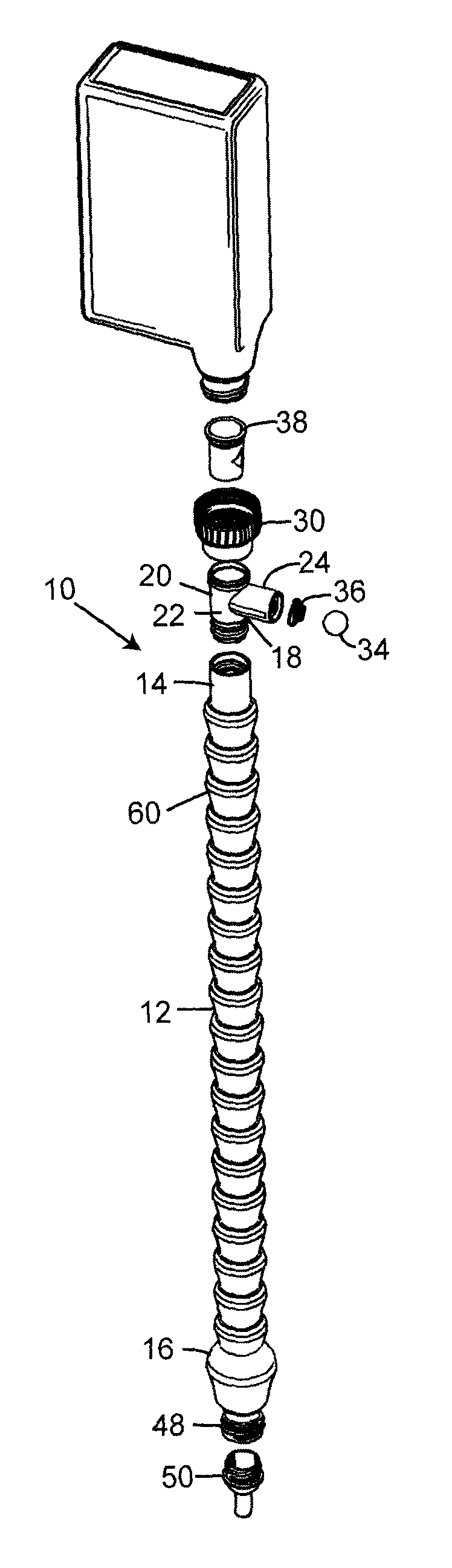
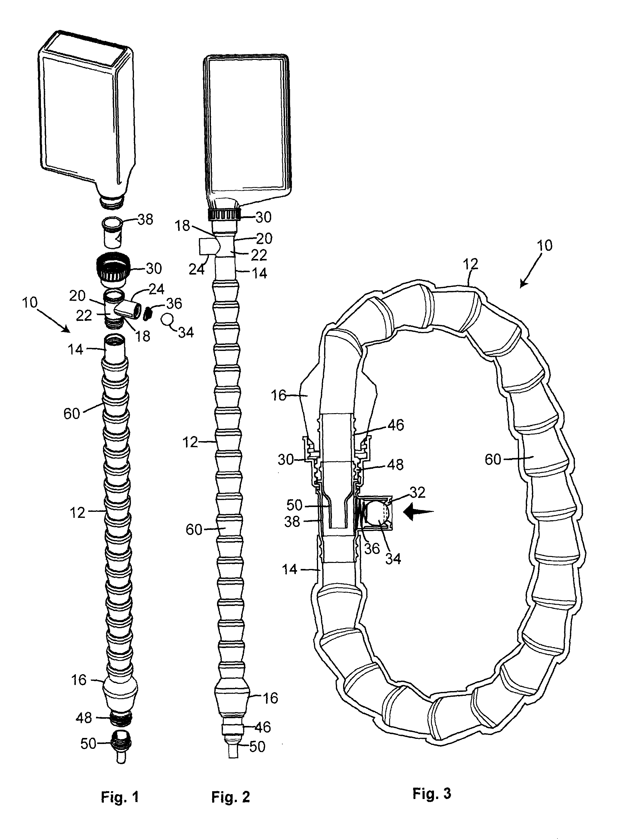
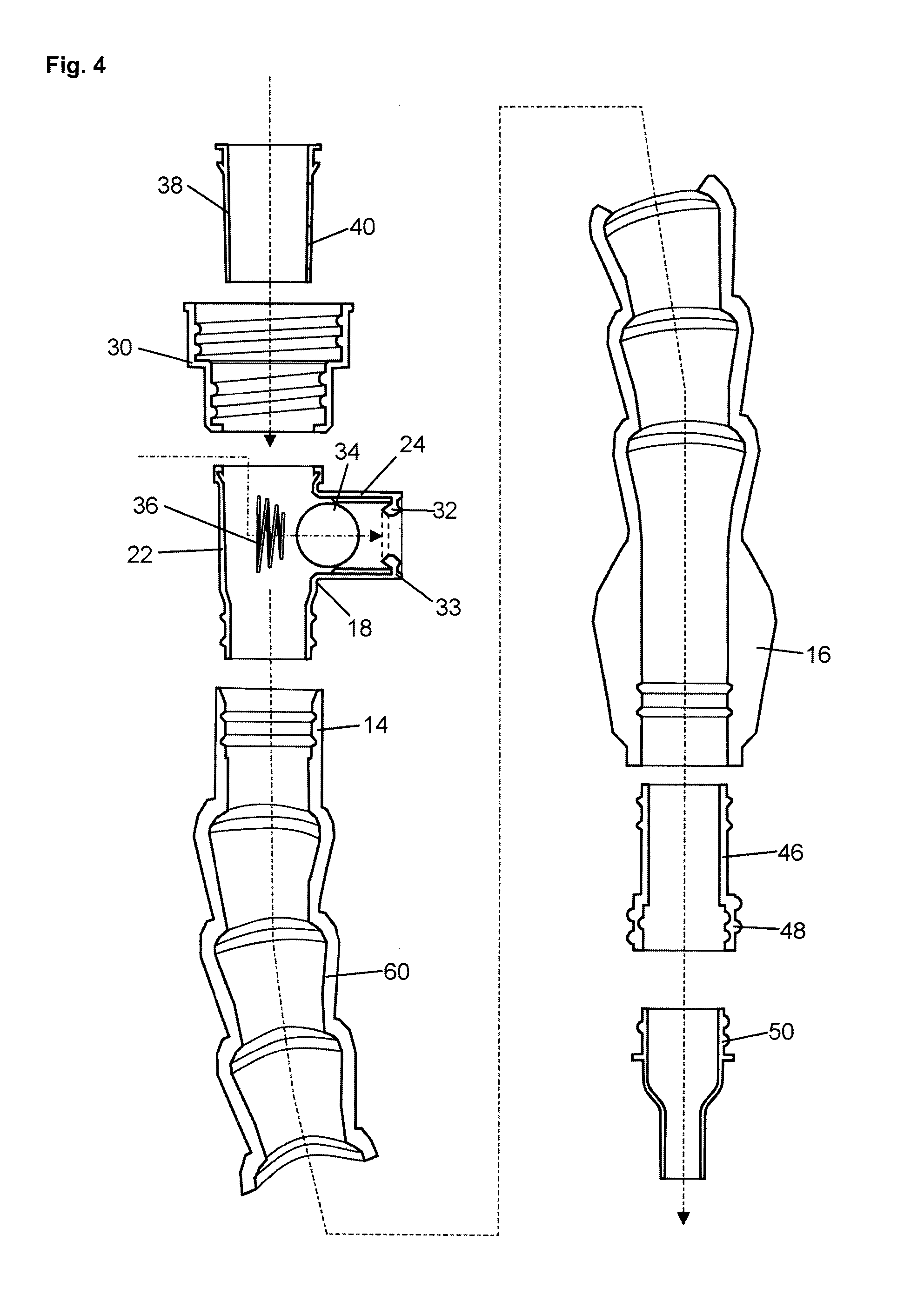
[0034]Referring to the drawings and particularly FIGS. 1-5, by reference characters, the flexible pouring spout 10 of the present invention includes a length of a flexible hose or tubing 12 having a first end such as inlet end 14 and terminal end such as outlet end 16. The flexible tubing 12 may be a convoluted plastic or rubber tu...


PUM


Abstract

A flexible pouring spout of segmented tubing having an internally threaded adapter cap at one end for connecting with a threaded neck of a fluid container, and an externally threaded terminal end which is adapted to connecting with the adapter cap thereby enabling the device to form a loop of itself. Thus, the interior of the spout remains clean even if it has a sticky or oily substance thereon, and any fluid within the device is retained therein. Also provided is a sealable air inlet valve for allowing air to be drawn into the spout when in use to prevent fluid lock in the device and bottle collapse, and to facilitate rapid and efficient pouring of the fluid from its container.

Description

BACKGROUND OF THE INVENTION[0001]1. Field of the Invention[0002]The present invention generally relates to spouts and funnels for fluids, and more particularly to elongate flexible pouring spouts for pouring fluid from a container into relatively narrow orifice or opening, such as for example, pouring automotive fluids from their containers into receptacles for same on motor vehicles.[0003]2. Description of Related Art[0004]One difficulty with some prior art funnels or elongated flexible pouring spouts is that they frequently become contaminated, particularly if they are used with some sticky substance such as oil, coolant and the like. When such spout is not in use, the oily surface of the interior attracts and retains dust and dirt so that the next time the spout or funnel is used, the oil or other liquid becomes contaminated. Further, when such flexible spouts or funnels are hung up for storage, they tend to drip and cause unsightly stains and contamination of the underlying surf...

Claims


Application Information

Patent Timeline
IPC IPC(8): B67D3/00B67D7/00
CPCB67D7/005B65D25/48
Inventor ABELL, CAMERON
Owner EXPRESS PROD LLC
Why Eureka
Try Eureka