
Amorphous metals and composites as mirrors and mirror assemblies

a technology of composites and mirrors, applied in the field of mirror structures, can solve the problems of unexplored research on ams and composites as mirror assemblies (especially formed in one step), and achieve the effects of reducing the cost of mirrors, reducing the cost of fabrication, and robust scratch resistance of ams

Active Publication Date: 2013-06-06
CALIFORNIA INST OF TECH
View PDF4 Cites 60 Cited by
  • Summary
  • Abstract
  • Description
  • Claims
  • Application Information

AI Technical Summary

Benefits of technology

The patent describes a method to make mirrors that can be cast into both the surface and the backing in one step, which can reduce the cost of the mirror. These mirrors are useful in space applications and have many terrestrial applications as well. The method uses a process called AMs, which are resistant to scratches and can be made at a lower cost.

Problems solved by technology

The technical problem addressed in this patent is the lack of investigation and understanding of the mechanical properties and processing ability of amorphous metals and composites when formed as mirror assemblies. The invention aims to provide a solution by using bulk metallic glasses, which are amorphous metals with a thickness greater than 1 mm.

Method used


Image

  • Amorphous metals and composites as mirrors and mirror assemblies
  • Amorphous metals and composites as mirrors and mirror assemblies
  • Amorphous metals and composites as mirrors and mirror assemblies

Examples


process embodiments

[0231]In one or more embodiments, a method of fabricating a mirror or mirror assembly, comprises:

[0232](a) heating (Block 3400) an amorphous metal (AM), bulk metallic glass (BMG) or bulk metallic glass matrix composite (BMGMC) locally or in total;

[0233](b) forming (Block 3402) the heated material into a mirror or mirror assembly;

[0234](c) removing (Block 3406) the material from the mold or heating source; and

[0235](d) if necessary, performing a finishing step that could include surface treating, deposition of a layer, joining, welding, embossing or assembly to create the final part.

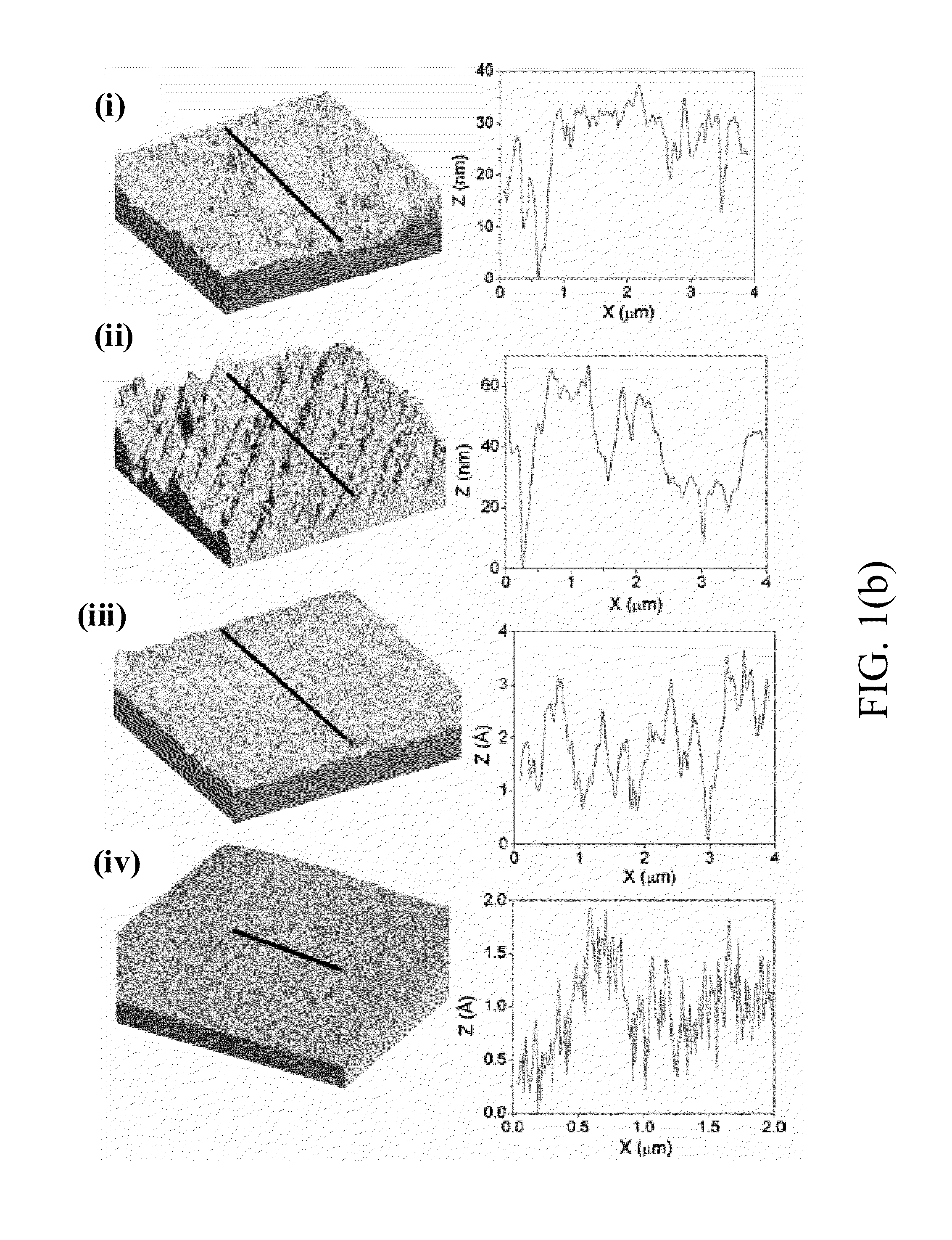
[0236]In one or more embodiments, an optically smooth surface (Block 3410) with roughness less than 0.1 micrometers is formed without grinding or polishing the sample wherein (a) the surface is formed by die-casting (in Block 3402) from a liquid against a mirror polished mold (the liquid BMG or BMGC formed by heating in Block 3400); (b) the surface is formed by thermoplastic forming (in Block 3402) in the...


PUM

PropertyMeasurementUnit
Temperatureaaaaaaaaaa

Abstract

A mirror or mirror assembly fabricated by molding, pressing, assembling, or depositing one or more bulk metal glass (BMG), bulk metal glass composite (BMGMC), or amorphous metal (AM) parts and where the optical surface and backing of the mirror can be fabricated without machining or polishing by utilizing the unique molding capabilities of this class of materials.

Description


Claims


Application Information

Patent Timeline
Owner CALIFORNIA INST OF TECH
Learn More