Grain-oriented electrical steel sheet and method of manufacturing the same
a technology of electrical steel sheet and grain orientation, which is applied in the manufacture of magnetic cores, magnetic bodies, magnetic materials, etc., can solve the problems of high passing speed, insufficient subdivision of magnetic domain, and significant reduction of productivity, and achieve the effect of low iron loss
- Summary
- Abstract
- Description
- Claims
- Application Information
AI Technical Summary
Benefits of technology
Problems solved by technology
Method used
Image
Examples
first experiment
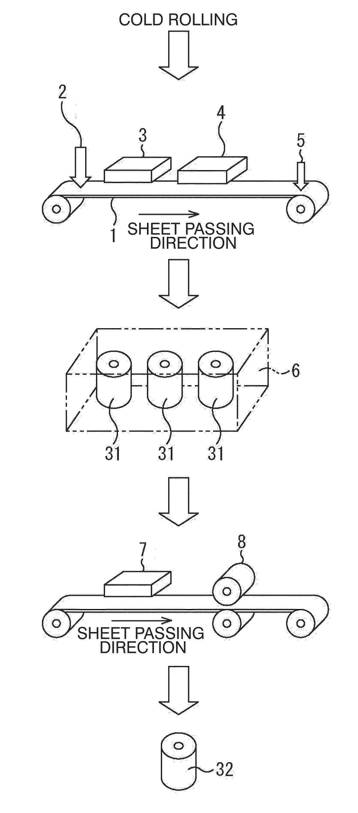
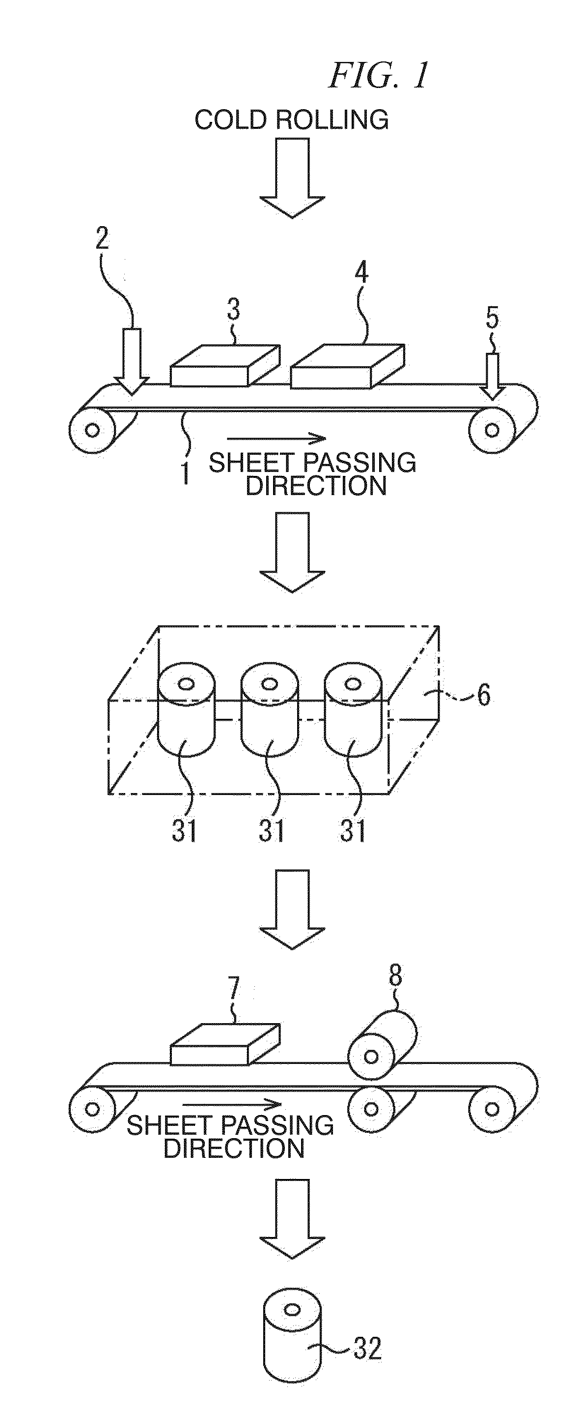
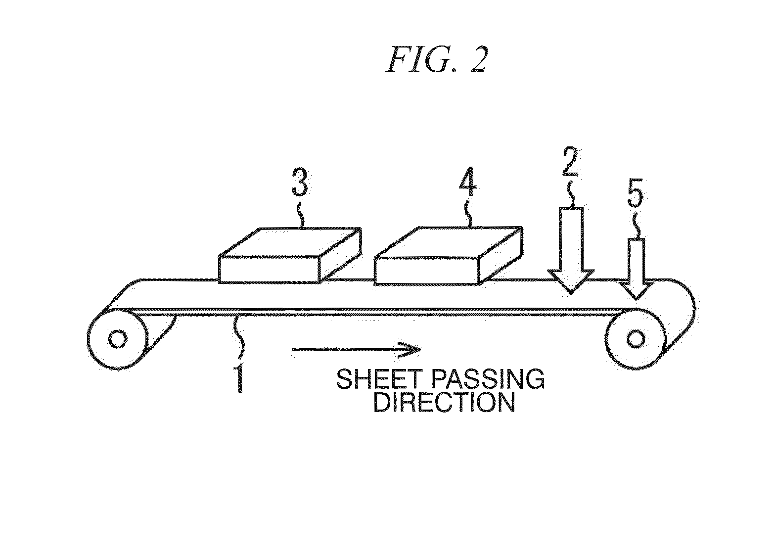
[0065]In a first experiment, hot rolling, annealing, and cold rolling of a steel material for oriented electrical steel were performed, the thickness of the silicon steel sheet was set to be 0.23 mm, and the silicon steel sheet was wound, thereby being turned into a cold-rolled coil. Five cold-rolled coils were produced. Subsequently, with respect to three cold-rolled coils related to Example Nos. 1, 2, and 3, the formation of the groove by the irradiation of the laser beam was performed and thereafter, the decarburization annealing was performed, thereby causing the primary recrystallization. The irradiation of the laser beam was performed by using a fiber laser. In all the examples, the power P was 2000 W, and with respect to a focused shape, in Example Nos. 1 and 2, the diameter Dl in the L direction was 0.05 mm and the diameter Dc in the C direction was 0.4 mm. With respect to Example No. 3, the diameter Dl in the L direction was 0.04 mm and the diameter Dc in the C direction wa...
second experiment
[0071]In a second experiment, verification regarding the irradiation conditions of the laser beam was performed. Here, the irradiation of the laser beam was performed in four types of conditions described below.
[0072]In a first condition among the four type conditions, a continuous-wave fiber laser was used. The power P was set to be 2000 W, the diameter Dl in the L direction was set to be 0.05 mm, the diameter Dc in the C direction was set to be 0.4 mm, and the scanning speed Vc was set to be 5 m / s. Therefore, the instantaneous power density Ip was 127 kW / mm2 and the irradiation energy density Up was 10.2 J / mm2. That is, compared to the conditions of the first experiment, the scanning speed was reduced by half, and thus the irradiation energy density Up was doubled. Therefore, the first condition does not satisfy Formula 3. As a result, warp deformation of the steel sheet was generated with an irradiated portion as the starting point. Since a warp angle reached a range of 3° to 10°...
third experiment
[0076]In a third experiment, the irradiation of the laser beam was performed under two sets of conditions, a condition in which the flow rate of the assist gas was set to be less than 10 L / minute and a condition in which the assist gas is not supplied. As a result, it was difficult to stabilize the depth of the groove, variation in the width of the groove was greater than or equal to range of ±10 μm, and variation in the depth was greater than or equal to range of ±5 μm. For this reason, variation in magnetic characteristics was large, compared with the examples.
PUM
| Property | Measurement | Unit |
|---|---|---|
| grain diameter | aaaaa | aaaaa |
| grain diameter | aaaaa | aaaaa |
| width | aaaaa | aaaaa |
Abstract
Description
Claims
Application Information
 - R&D
- Intellectual Property
- Life Sciences
- Materials
- Tech Scout
- Unparalleled Data Quality
- Higher Quality Content
- 60% Fewer Hallucinations
Browse by: Latest US Patents, China's latest patents, Technical Efficacy Thesaurus, Application Domain, Technology Topic, Popular Technical Reports.
© 2025 PatSnap. All rights reserved.Legal|Privacy policy|Modern Slavery Act Transparency Statement|Sitemap|About US| Contact US: help@patsnap.com


