Two-beam interference apparatus and two-beam interference exposure system
a two-beam interference and exposure system technology, applied in the field of twobeam interference apparatus and two-beam interference exposure system, can solve problems such as deterioration
- Summary
- Abstract
- Description
- Claims
- Application Information
AI Technical Summary
Benefits of technology
Problems solved by technology
Method used
Image

Examples
first embodiment
[0078]3. Two-Beam Interference Exposure System (First Embodiment)
[0079]First, a detailed description will be given with respect to the two-beam interference exposure system in a first embodiment of the present disclosure, with reference to the drawings.
[0080]3.1 Configuration
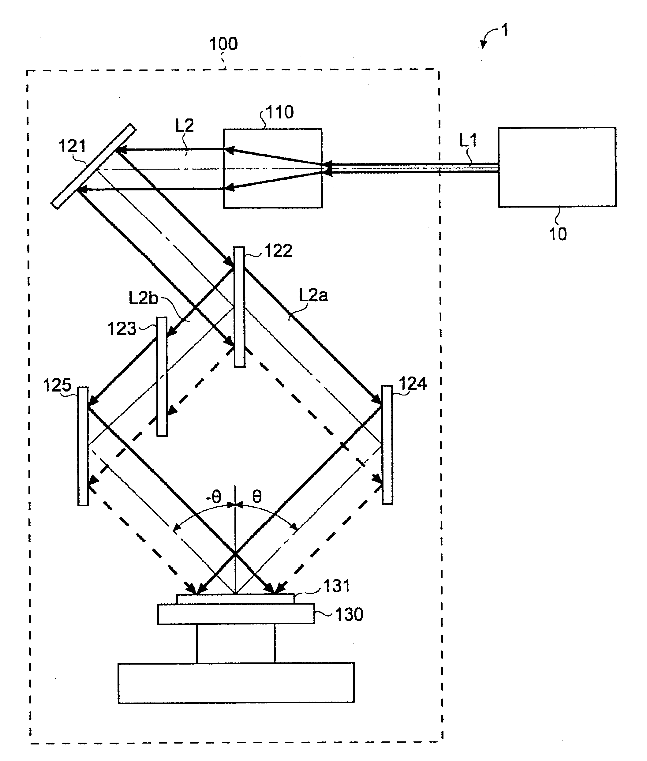
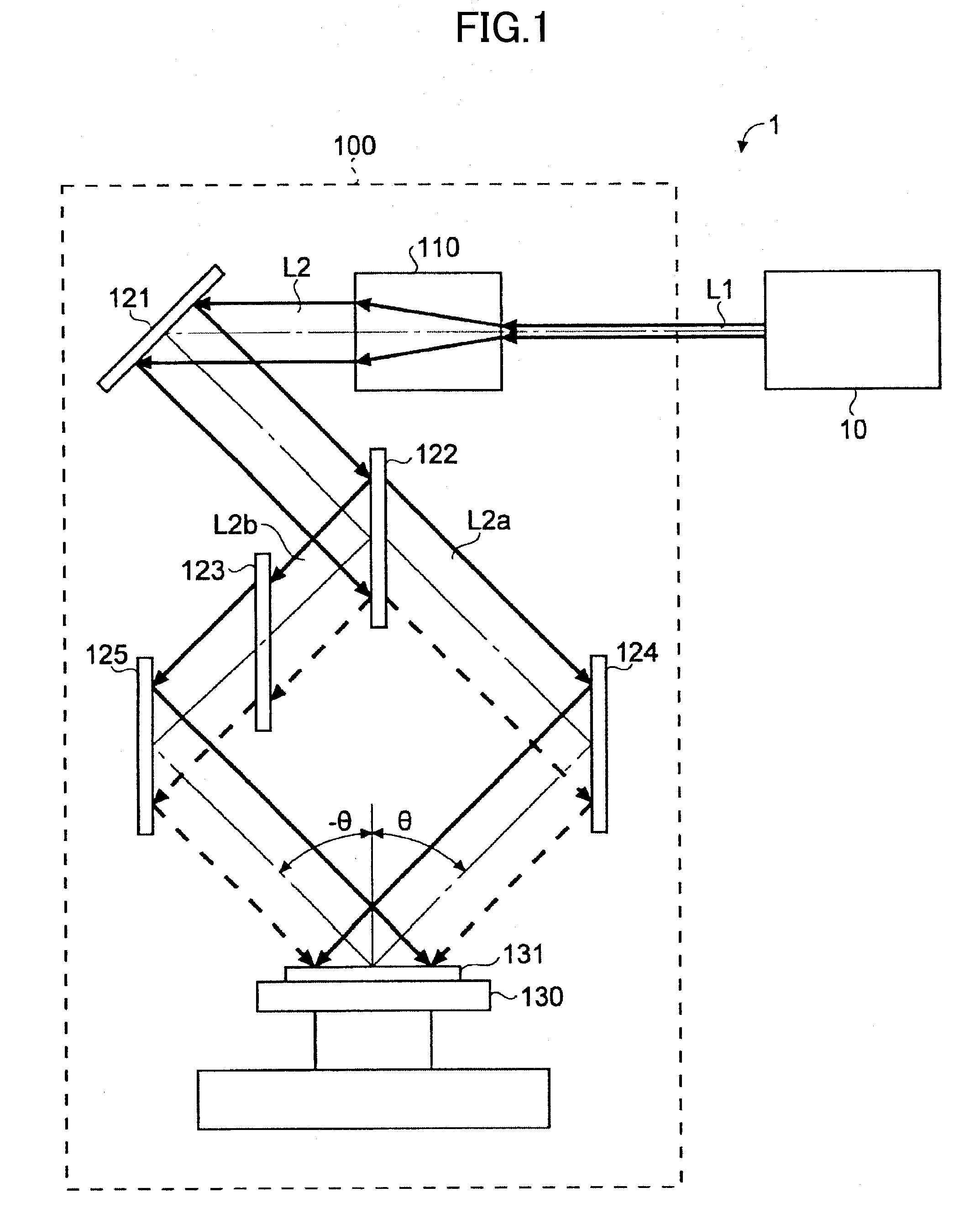
[0081]FIG. 1 is a diagram schematically illustrating a configuration of a two-beam interference exposure system 1 in the first embodiment. As illustrated in FIG. 1, the two-beam interference exposure system 1 may include a laser device 10 and a two-beam interference apparatus 100.
[0082]The laser device 10 may output ultraviolet laser light. For example, the laser device 10 may be formed by an ultraviolet laser device that outputs laser light L1 in a wavelength band of KrF (248.4 nm) or ArF (193.4 nm).
[0083]The two-beam interference apparatus 100 may include a beam tuning unit 110, a high reflection mirror 121, a beam splitter 122, an optical path correcting plate 123, a high reflection mirrors 124 and 125, and a...
second embodiment
[0102]4. Two-Beam Interference Exposure Apparatus With Tunable Beam Profile (Second Embodiment)
[0103]Next, a detailed description will be given of the two-beam interference exposure system in a second embodiment of the present disclosure, with reference to the drawings. In the following description, those constituent elements that are similar to those described above are designated by the same reference characters, and redundant description thereof will be omitted.
[0104]4.1 Configuration
[0105]FIG. 3 is a diagram schematically illustrating a configuration of a two-beam interference exposure system 2 in the second embodiment. As illustrated in FIG. 3, the two-beam interference exposure system 2 may include a laser device 10 and a two-beam interference apparatus 200. The two-beam interference apparatus 200 may have a configuration similar to that of the two-beam interference apparatus 100 illustrated in FIG. 1. However, the beam tuning unit 110 may be replaced by a beam tuning unit 210...
third embodiment
[0113]5. Two-Beam Interference Exposure System Using Narrow Band Excimer Laser Device (Third Embodiment)
[0114]Next, a detailed description will be given of the two-beam interference exposure system in a third embodiment of the present disclosure, with reference to the drawings. In the following description, those constituent elements that are similar to those described above are designated by the same reference characters, and redundant description thereof will be omitted.
[0115]5.1 Configuration
[0116]FIG. 6 is a diagram schematically illustrating a configuration of a two-beam interference exposure system 3 in the third embodiment. As illustrated in FIG. 6, the two-beam interference exposure apparatus 3 may include an excimer laser device 20 and a two-beam interference apparatus 300. The excimer laser device 20 may be a KrF excimer laser or an ArF excimer laser, for example. The two-beam interference apparatus 300 may have a configuration similar to that of the two-beam interference ...
PUM
 Abstract
Description
Claims
Application Information
 - R&D
- Intellectual Property
- Life Sciences
- Materials
- Tech Scout
- Unparalleled Data Quality
- Higher Quality Content
- 60% Fewer Hallucinations
Browse by: Latest US Patents, China's latest patents, Technical Efficacy Thesaurus, Application Domain, Technology Topic, Popular Technical Reports.
© 2025 PatSnap. All rights reserved.Legal|Privacy policy|Modern Slavery Act Transparency Statement|Sitemap|About US| Contact US: help@patsnap.com