Rotary actuator

Active Publication Date: 2013-05-30
NABLESCO CORP
View PDF12 Cites 44 Cited by
  • Summary
  • Abstract
  • Description
  • Claims
  • Application Information

AI Technical Summary

Benefits of technology

The present invention provides a rotary actuator that can reduce internal leakage of the pressure medium and does not require high-pressure rotary seals. This is achieved by using a separate tubular hollow member to define the piston chamber, which results in a seamless surface for sliding and further reduces internal leakage.

Problems solved by technology

Unfortunately, it is difficult to suppress leakage of the pressure fluid in the rotary sliding portions by means of the seals.
Therefore, the pressure fluid often leaks within the rotary actuator.
Moreover, the conventional rotary actuators have a structure in which the seals are inserted into the grooves in the ribs or the vanes, the problem of leakage between the grooves and the seals also arises.
Furthermore, since each seal inserted into the groove has corner sections, it is particularly difficult to maintain adhesion to the surface relative to which the seal slides, in those corner sections and in the vicinity thereof, which makes it difficult to suppress leakage.
Therefore, the pressure fluid leaks more often within the rotary actuator.
In addition, the conventional rotary actuators need high-pressure rotary seals that are used in the rotary sliding portions and pressed with high pressure against the surface relative to which the seals slide.
Such seals are therefore different from statically used seals or those for use in linear sliding portions, and another problem arises of significantly shorter duration of the seals during which sealing characteristics intended by the design can be maintained.

Method used


Image

  • Rotary actuator
  • Rotary actuator
  • Rotary actuator

Examples


Embodiment Construction

[0037]An embodiment for implementing the present invention will be hereinafter described with reference to the drawings. Note that the present invention can be applied widely to rotary actuators that output driving torque as a result of output shafts thereof pivoting in a rotational direction due to action of a pressure medium.

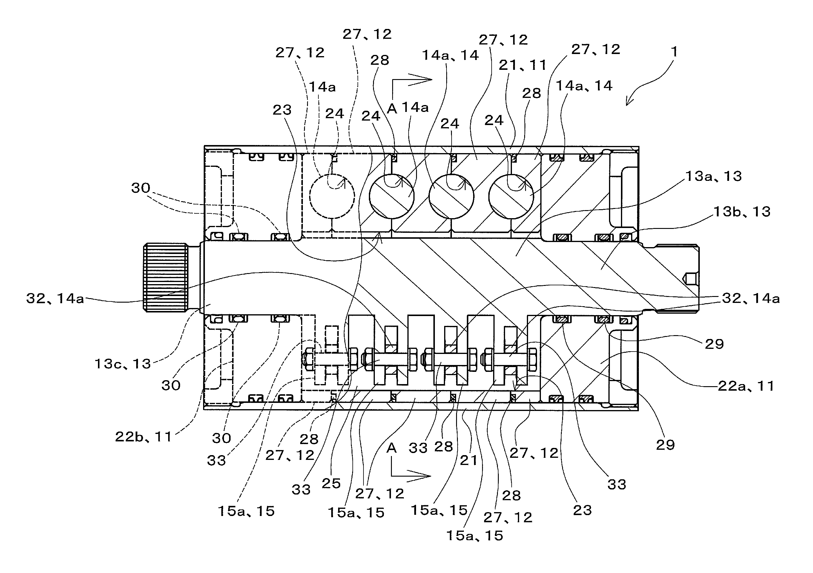
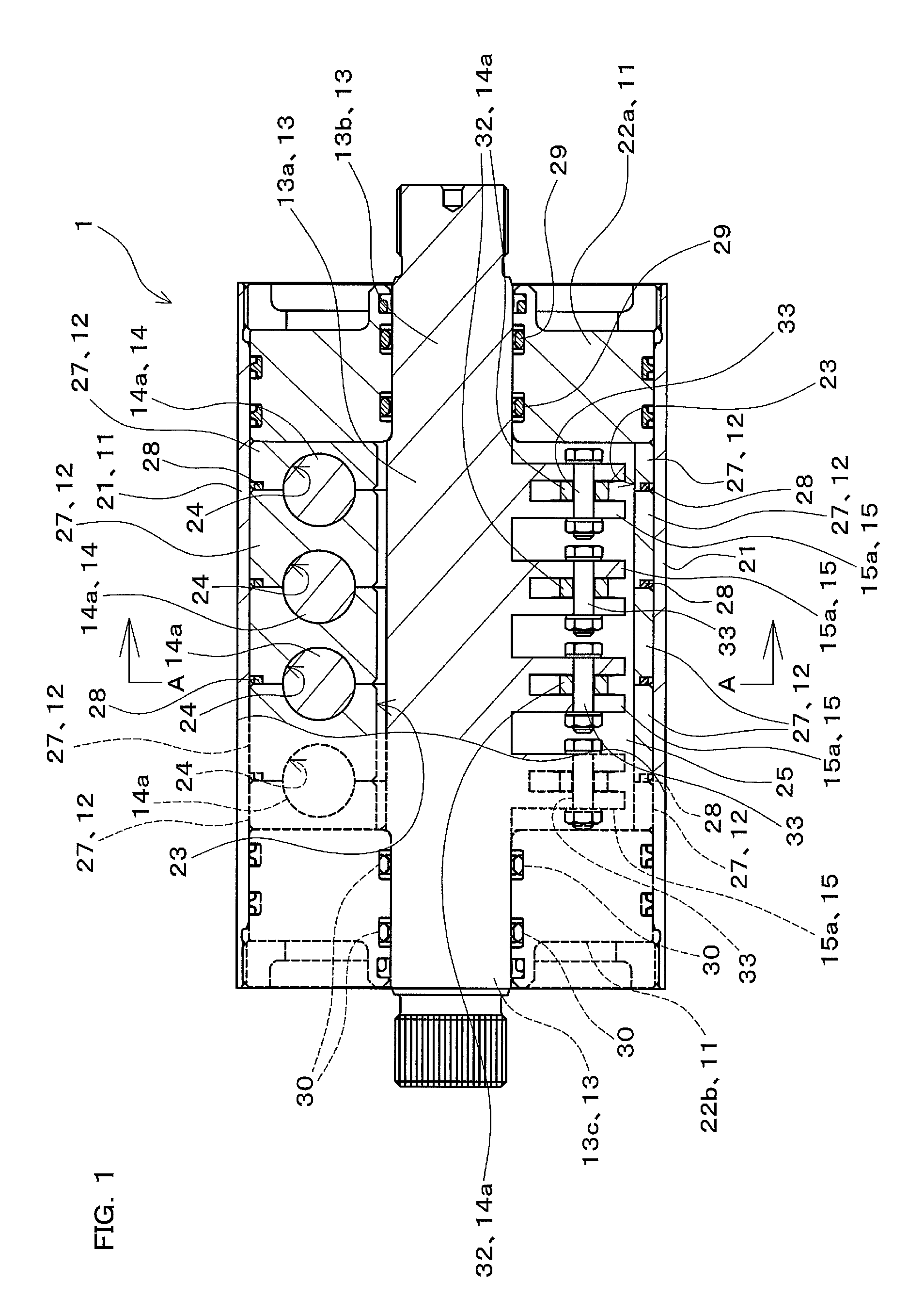
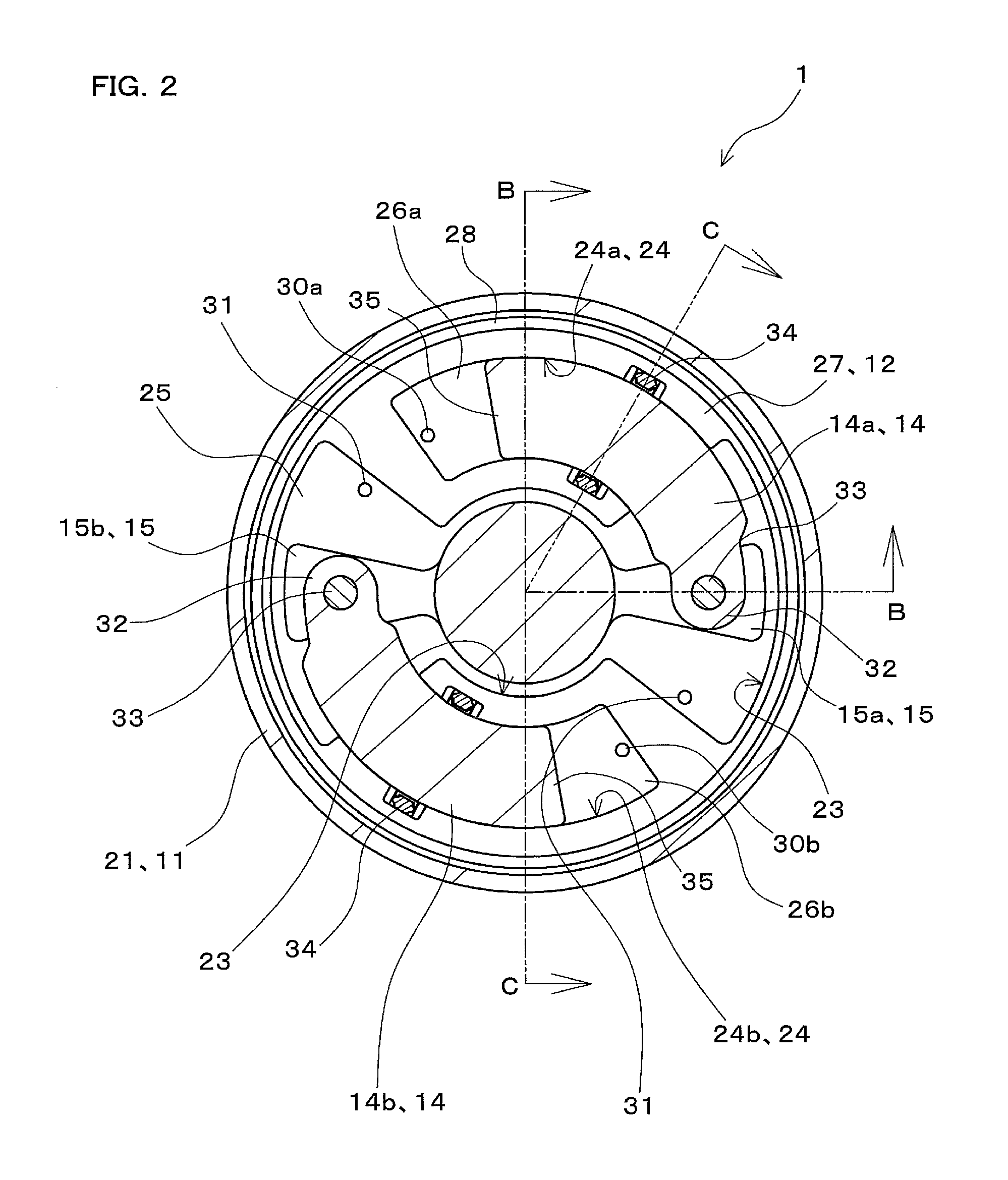
[0038]FIG. 1 is a diagram showing a rotary actuator 1 according to one embodiment of the present invention including a partial cross-sectional view thereof, viewed from a direction perpendicular to an axial direction thereof. FIG. 2 is a cross-sectional view of the rotary actuator 1, viewed along arrows A-A in FIG. 1. Note that FIG. 1 includes the cross section viewed along arrows B-B indicated by dashed lines in FIG. 2. FIG. 3 is a diagram showing the rotary actuator 1 including a cross-sectional view thereof, viewed along arrows C-C indicated by two-dot chain lines in FIG. 2.

[0039]The rotary actuator 1 shown in FIGS. 1 to 3 is provided as an actuator that ou...


PUM


Abstract

A cylinder is installed within a case, and an output shaft and an arm that is integrated thereto and extends in a radial direction are installed within the cylinder. A piston extending in an arc slides and is displaced in a circumferential direction of the cylinder within the cylinder. One end portion of the piston is rotatably connected to the arm. The cylinder is internally provided with a first pressure chamber in which the arm is housed and a second pressure chamber in which the other end portion of the arm is slidably installed. A pressure medium is fed into one of the first and second pressure chambers and discharged from the other, and the output shaft pivots in a rotational direction.

Description

CROSS-REFERENCE TO RELATED APPLICATION[0001]This application claims priority to Japanese Patent Application No. 2011-258508. The entire disclosure of Japanese Patent Application No. 2011-258508 is hereby incorporated herein by reference.BACKGROUND OF THE INVENTION[0002]1. Field of the Invention[0003]The present invention relates to rotary actuators that output driving torque as a result of output shafts pivoting in a rotational direction due to action of a pressure medium.[0004]2. Description of the Related Art[0005]A rotary actuator having such a configuration as the one disclosed in U.S. Pat. No. 5,601,165 is known as one of the rotary actuators that output driving torque as a result of an output shaft pivoting in a rotational direction due to action of a pressure fluid serving as a pressure medium.[0006]In the rotary actuator disclosed in U.S. Pat. No. 5,601,165, ribs are provided within a cylinder as an integral unit, and vanes are provided to an output shaft rotatably installed...

Claims


Application Information

Patent Timeline
IPC IPC(8): F04C9/00
CPCF04C9/00F01C9/002F01C11/002F04C2240/60F01C21/08F04C15/0076F04C2240/30F01C20/02
Inventor ITO, KOJI
Owner NABLESCO CORP
Why Eureka
Try Eureka