
Apparatus and method for controlling charging power of wireless power receiver

a wireless power receiver and charging power technology, applied in the direction of charging/discharging, charge maintainance, transportation and packaging, etc., can solve the problem of limiting the magnitude of wireless power that the conventional wireless power transmitter unit can supply, the inconvenience of wireless power transmission by some wireless power receiver units, and the interruption of wireless power transmission

Active Publication Date: 2013-05-23
SAMSUNG ELECTRONICS CO LTD
View PDF9 Cites 55 Cited by
  • Summary
  • Abstract
  • Description
  • Claims
  • Application Information

AI Technical Summary

Benefits of technology

The invention aims to solve the problem where a wireless power transmitter can only output a certain amount of power. When multiple wireless power receivers request charging simultaneously, the invention provides a way to adjust the required power to ensure efficient charging. This is done by a transmission apparatus that calculates the sum of the required charging powers of the receivers and generates a charging power adjustment signal for the receivers to adjust their charging power. A reception apparatus then receives the charging power adjustment signal and adjusts its charging power accordingly. The technical effect of the invention is to improve wireless charging efficiency.

Problems solved by technology

As described above, there is a limit on the magnitude of wireless power that the conventional wireless power transmitter unit can supply.
Accordingly, there is a problem in that the wireless power transmission can be interrupted.
As such, there is an inconvenience in that some wireless power receiver units can receive wireless power, whereas other wireless power receiver units may not receive wireless power.

Method used


Image

  • Apparatus and method for controlling charging power of wireless power receiver
  • Apparatus and method for controlling charging power of wireless power receiver
  • Apparatus and method for controlling charging power of wireless power receiver

Examples


Embodiment Construction

[0024]Hereinafter, embodiments of the present invention will be described in detail with reference to the accompanying drawings. In the following description and the accompanying drawings, a detailed description of publicly-known functions and configurations which may unnecessarily obscure the subject matter of the present invention, will be omitted.

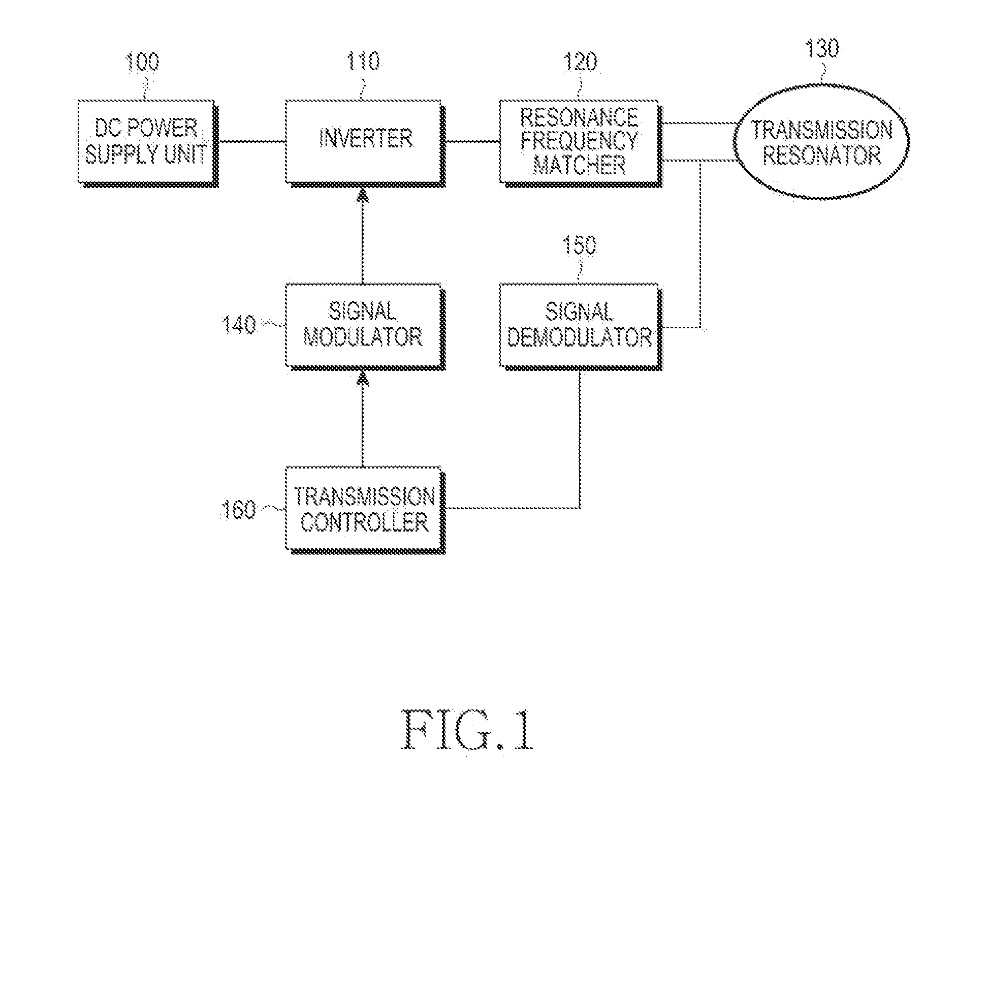
[0025]FIG. 1 illustrates a configuration of a wireless power transmitter according to an embodiment of the present invention.

[0026]The wireless power transmitter includes a DC (Direct Current) power supply unit 100, an inverter 110, a resonance frequency matcher 120, a transmission resonator 130, a signal modulator 140, a signal demodulator 150, and a transmission controller 160.

[0027]The DC power supply unit 100 outputs a DC power signal for charging a power source of a wireless power receiver.

[0028]The inverter 110 converts a DC power signal to an AC (Alternating Current) power signal.

[0029]The resonance frequency matcher 120 performs ...


PUM


Abstract

In an apparatus for adjusting charging power of a wireless power receiver, when one or more wireless power receivers require charging, it is determined whether the sum of required charging powers required by the one or more wireless power receivers exceeds maximum supplied power provided by a wireless power transmitter. When a result indicates that the sum exceeds the maximum supplied power, a control operation is performed to adjust the required charging power of each wireless power receiver. Therefore, it is possible to wirelessly charge each wireless power receiver without interruption.

Description

PRIORITY[0001]This application claims priority under 35 U.S.C. 119(a) to Korean Patent Application Serial No. 10-2011-0120828, which was filed in the Korean Intellectual Property Office on Nov. 18, 2011, the contents of which are incorporated herein by reference.BACKGROUND OF THE INVENTION[0002]1. Field of the Invention[0003]The present invention relates generally to an apparatus for controlling charging power, and more particularly, to an apparatus and a method for controlling a total required power of one or more wireless power receivers during a charging of a relevant wireless power receiver.[0004]2. Description of the Related Art[0005]Wireless power transmission technology has recently been utilized for many electronic devices, such as electric toothbrushes, electric shavers, mobile phones, and digital cameras. Studies are also being conducted on improved wireless charging of large batteries, e.g., for electric cars and subway trains.[0006]Wireless power transmission technologie...

Claims


Application Information

Patent Timeline
Patent Type & Authority Applications(United States)
IPC IPC(8): H02J7/00
CPCH02J7/007H02J7/0052H02J7/025H02J5/005H02J7/0077H02J1/14H02J7/00712H02J50/80H02J50/12H02J50/50H02J7/0069
Inventor PARK, SUNG-KWEONLEE, YOUNG-MINKO, KIL-SOOKIM, KI-HYUNPARK, SE-HOPARK, JIN-HYOUNG
Owner SAMSUNG ELECTRONICS CO LTD
Learn More