Drive Circuit Structure for LED Lamp Tube

a technology of led lamp tube and drive circuit, which is applied in the direction of cathode-ray/electron beam tube circuit elements, lighting and heating apparatus, semiconductor devices for light sources, etc., can solve the problem that the size of the transformer b>131/b> in use is also unavoidably more voluminous, and the gap between these two led lamp straps is not uncommon

Inactive Publication Date: 2013-05-23
VERTICIL ELECTRONICS CORP
View PDF7 Cites 15 Cited by
  • Summary
  • Abstract
  • Description
  • Claims
  • Application Information

AI Technical Summary

Benefits of technology

[0010]The objective of the present invention is to provide a solution capable of preventing a large-sized electronic component from occupying larger accommodation space in order to drive an entire piece of LED lamp strap by means of a drive circuit in the LED lamp tube.

Problems solved by technology

However, such a configuration method of placing two LED lamp straps 12 respectively on left and right sides within the long-strapped lampshade 11 will inevitably lead to the occurrence of a gap between these two left and right LED lamp straps 12.
Nevertheless, driving an entire piece of LED lamp strap 12 of greater length indeed requires a bigger power source to provide sufficient drive power, so the size of the transformer 131 in use also unavoidably becomes more voluminous as the supplied electric power increases.

Method used


Image

  • Drive Circuit Structure for LED Lamp Tube
  • Drive Circuit Structure for LED Lamp Tube
  • Drive Circuit Structure for LED Lamp Tube

Examples


Embodiment Construction

[0024]The aforementioned and other technical contents, aspects and effects in relation with the present invention can be clearly appreciated through the detailed descriptions concerning the preferred embodiments of the present invention in conjunction with the appended drawings.

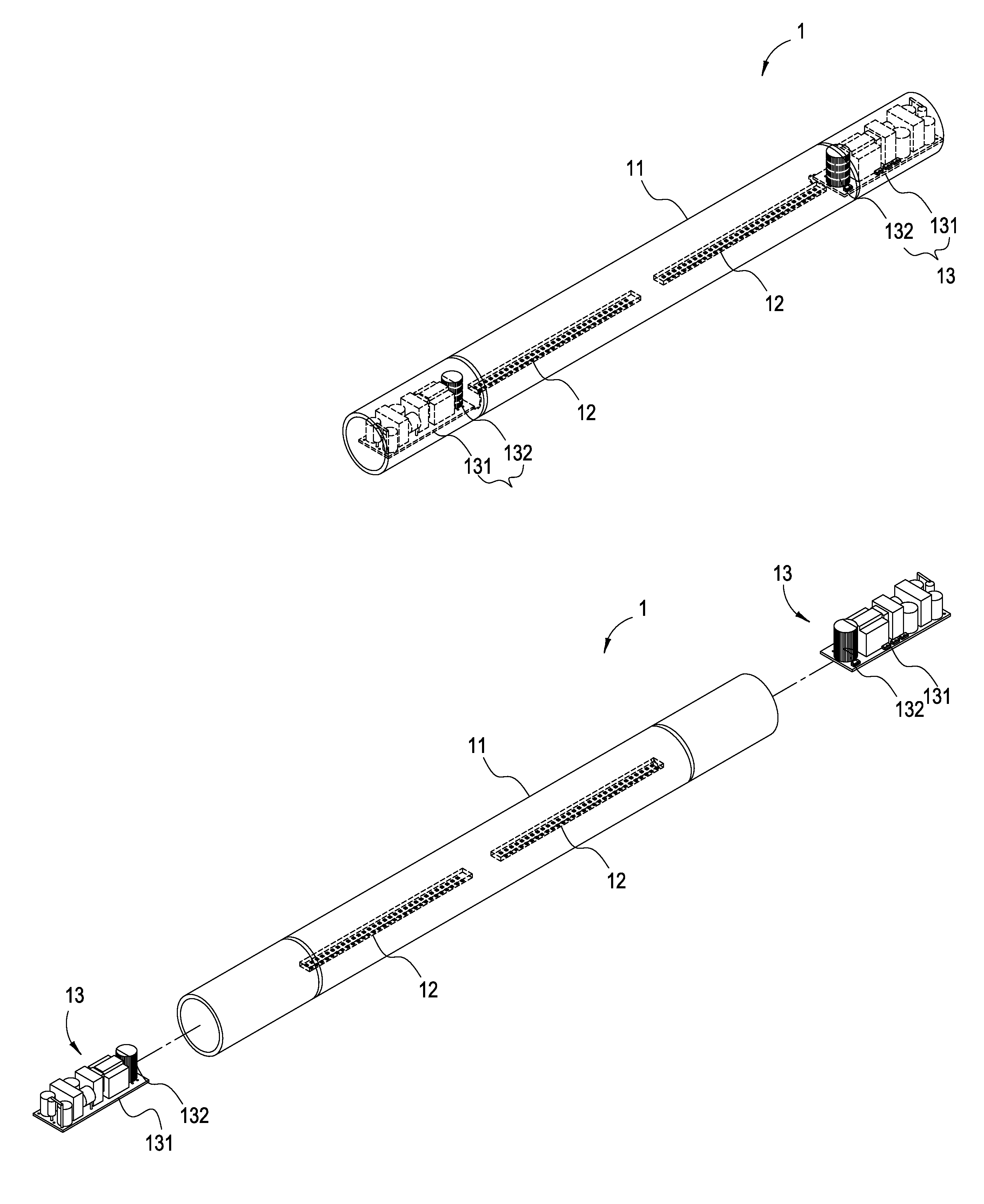
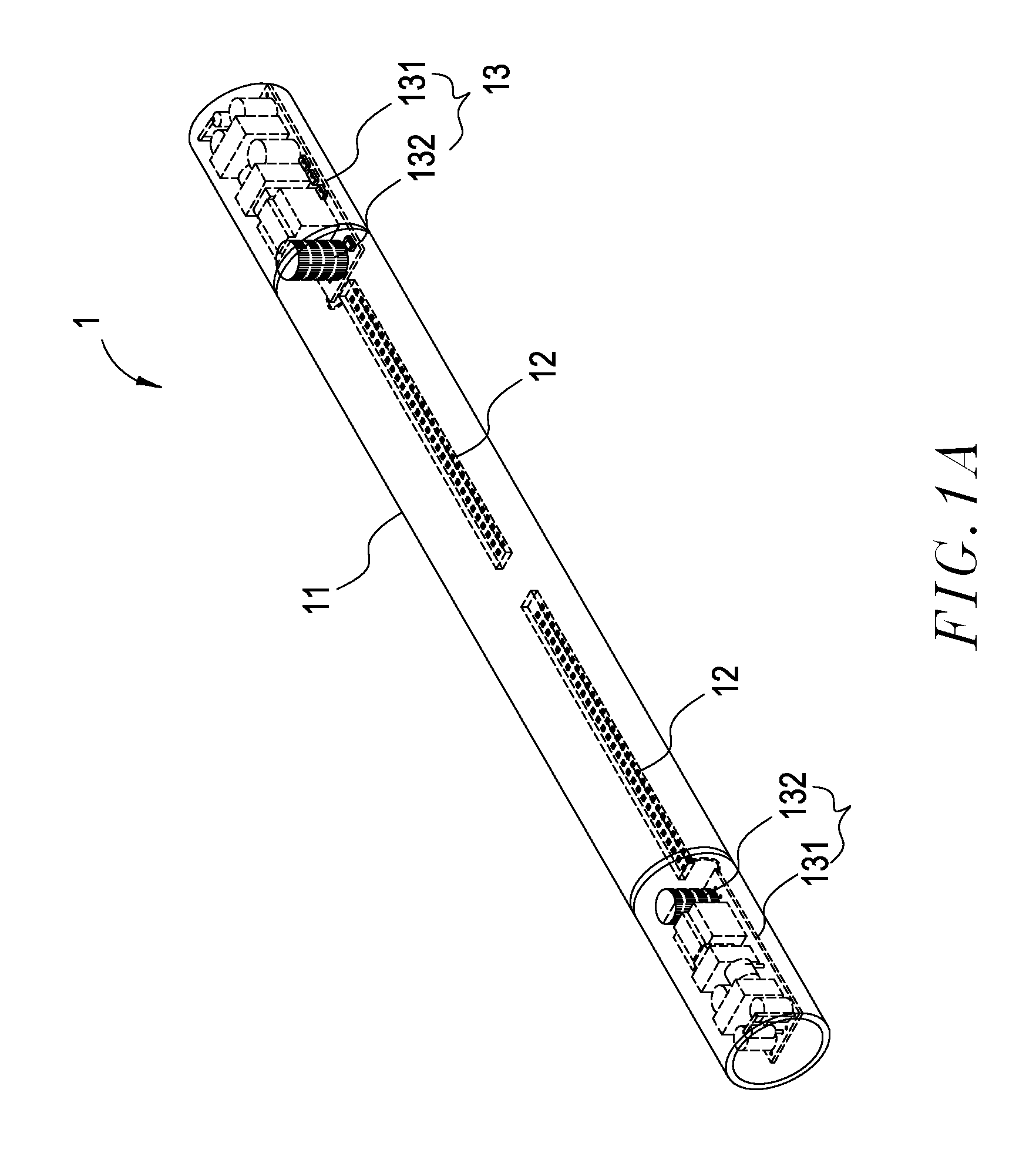
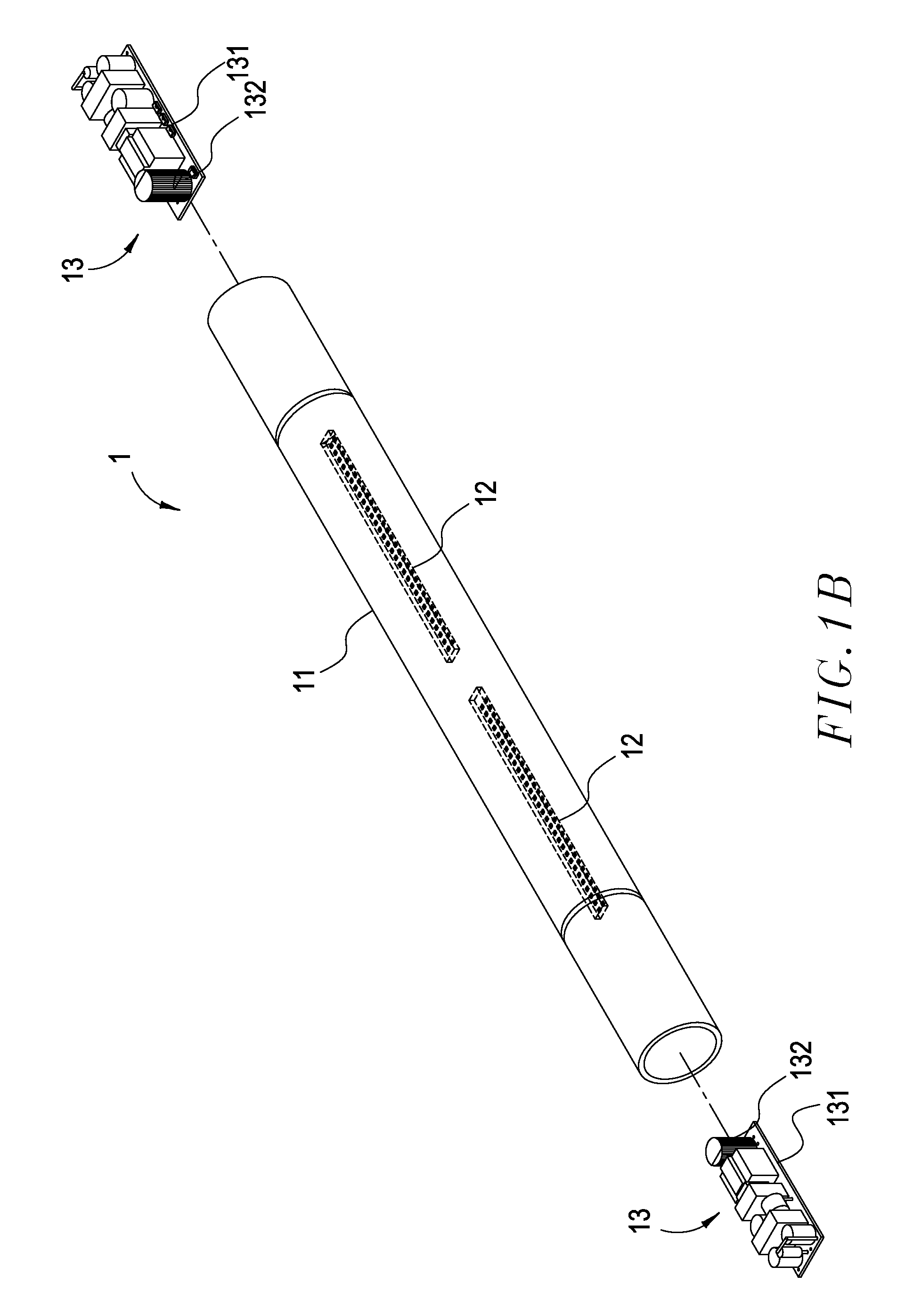
[0025]Refer next to FIG. 3, wherein a structural diagram of the drive circuit structure for LED lamp tube according to the present invention is shown. It can be seen from this figure that the drive circuit structure 23 comprises multiple general-sized electronic components 231 (for example, electronic components like resistors or capacitors and so forth), at least a large-sized electronic component 232 and a drive circuit board 233. Since it is to drive the LEDs 221 (the LED lamp) on the entire piece of the LED lamp strap 22, a transformer of larger size is required and accordingly represents the large-sized electronic component 232 indicated as above. It can be appreciated from the Figure that the large-size...


PUM


Abstract

A drive circuit structure for LED lamp tube is disclosed, wherein the LED lamp tube comprises a lampshade, at least an LED lamp strap and at least a drive circuit structure. The LED lamp strap is disposed inside the lampshade, and drive circuit structure connected with the LED lamp strap is disposed on any side within the lampshade. Moreover, the drive circuit structure includes multiple general-sized electronic components, at least a large-sized electronic component and a drive circuit board, wherein such general-sized electronic components are inserted on a plane of the drive circuit board, and the large-sized electronic component is disposed upright on any side of the drive circuit board. Accordingly, though the large-sized electronic component becomes voluminous, by disposing it upright on one side of the drive circuit board, it is possible to prevent the drive circuit structure from occupying larger accommodation space due to the large-sized electronic component.

Description

CROSS-REFERENCE TO RELATED APPLICATION[0001]The current application claims a foreign priority to the patent application of Taiwan No. 100222072 filed on Nov. 22, 2011.BACKGROUND OF THE INVENTION[0002]1. Field of the Invention[0003]The present invention generally relates to a drive circuit structure for light-emitting diode (LED) lamp tube. In particular, the present invention concerns a drive circuit structure installed in the interior of an LED lamp tube thereby preventing the large-sized electronic component from occupying larger accommodation space.[0004]2. Description of Related Art[0005]Featuring many advantages such as better power saving, longer life span, smaller size and faster reaction speed or the like, light emitting diodes (LEDs) are at present comprehensively applied in various illumination fields. Now certain manufacturers have developed the LED lamp tube allowable for replacement of fluorescent lamps. As shown in FIGS. 1A, 1B and 2, a general LED lamp tube 1 comprise...

Claims


Application Information

Patent Timeline
Patent Type & Authority Applications(United States)
IPC IPC(8): H01J7/44
CPCF21Y2103/003F21K9/175Y02B20/386F21V23/02F21Y2101/02F21V23/004F21Y2103/10F21Y2115/10F21V23/006F21K9/278F21K9/272Y02B20/30F21K9/27
Inventor LEE, CHENG-MINGJHENG, RUEI-JHIHLEE, FENG-PIN
Owner VERTICIL ELECTRONICS CORP
Why Eureka
Try Eureka