
Hybrid v-band coupling

a technology of v-band coupling and v-band, which is applied in the field of coupling, can solve the problems of labor and waste of material associated with manufacturing this type of products, and the associated expense of machining operations in order to remove materials, so as to eliminate expensive machining operations and material waste. , the effect of effective and efficient manner

Inactive Publication Date: 2013-05-23
VOSS INDS
View PDF0 Cites 13 Cited by
  • Summary
  • Abstract
  • Description
  • Claims
  • Application Information

AI Technical Summary

Benefits of technology

The patent describes a new design for a V-band coupling that is more cost-effective and can handle higher pressures than previous designs. The coupling includes a sheet metal band and three roll-formed retainers that securely seal high-pressure air. It also eliminates the need for expensive fasteners and machining operations. Overall, the new design is less expensive and more efficient than previous arrangements.

Problems solved by technology

One problem with machined rigid couplings is the expense of labor, and waste material associated with manufacturing this type of product.
Thus, a substantial amount of material is sometimes required to be removed from the original stock material, and there is also the associated expense of the machining operation in order to remove the material.
Another problem is that rigid couplings typically have two machined halves held together by links.
This can lead to potential leakage of the joint.
In cases where a valve is contained between the two flanges, the coupling can distort the flanges, which can cause the valve to improperly open and close.
This is undesirable, for example, in the bleed air systems of aircraft which is one use for couplings of this type.
Those V-band couplings which do have a safety latch feature are not nearly as robust as the latch used on rigid couplings.

Method used


Image

  • Hybrid v-band coupling
  • Hybrid v-band coupling
  • Hybrid v-band coupling

Examples


Embodiment Construction

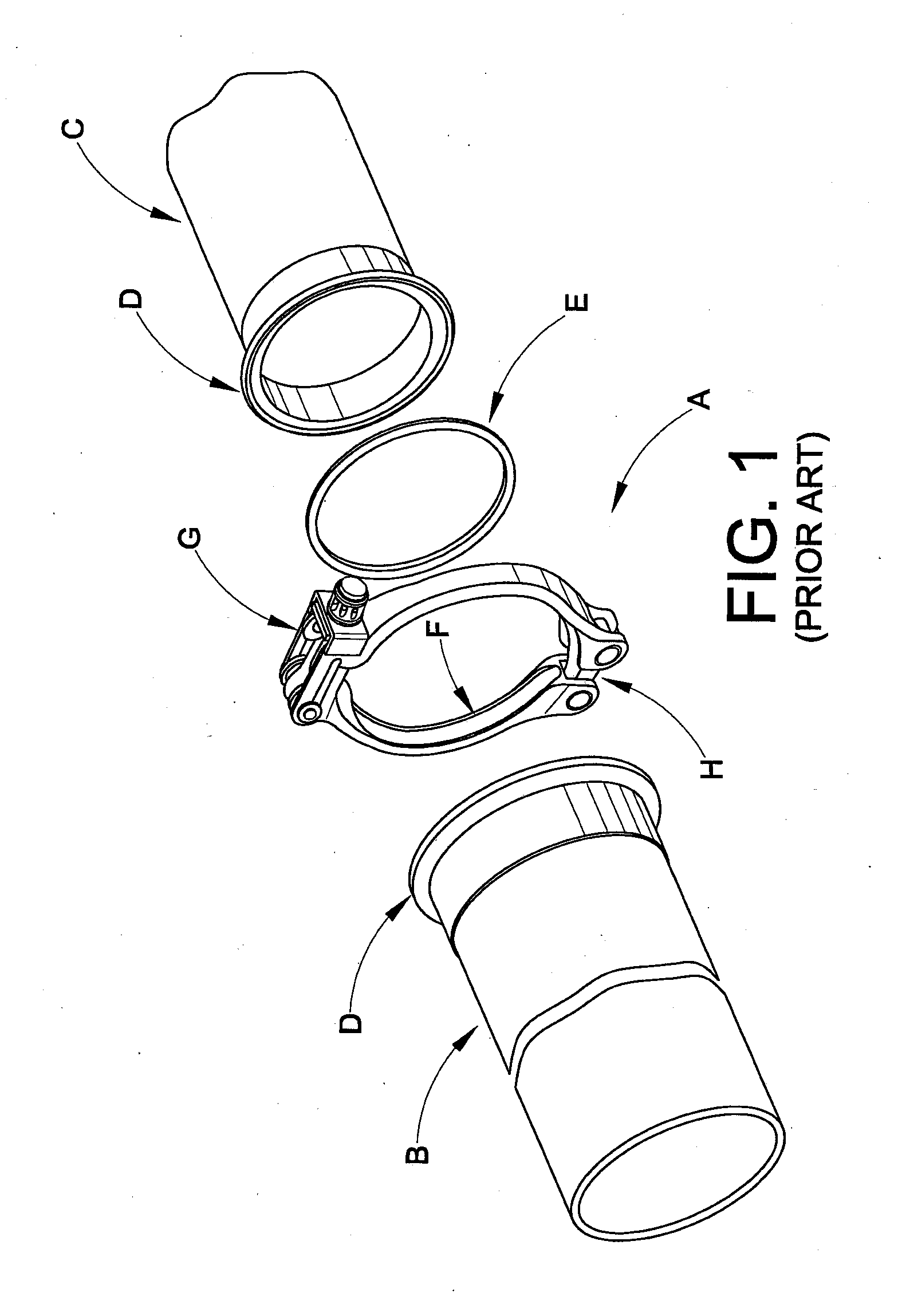
[0029]Turning first to FIG. 1, there is shown a conventional rigid coupling assembly A used for securing a pair of flanged ducts or tubular members B, C. Each of the tubular members B, C includes a flange D disposed adjacent a terminal end. The ends of the tubular members, and thus the individual flanges D, are brought into aligned, abutting relation and held in place by rigid V-retainers F (two rigid retainers in this instance) which are a part of the coupling assembly A. Oftentimes, a seal E is mainly received between the flanged ends of the tubular members. A latch assembly G secures first ends of the V-retainers F together, and second ends of the V-retainers are joined by a link assembly H. The conventional safety latch assembly includes a latch or saddle having a first leg, a second leg, and a connecting base wall. A trunnion washer or saddle block is secured via a fastener in the latch adjacent the sidewall thereof An eyebolt is pivotally secured to the first retainer half, se...


PUM

PropertyMeasurementUnit
Angleaaaaaaaaaa
Angleaaaaaaaaaa

Abstract

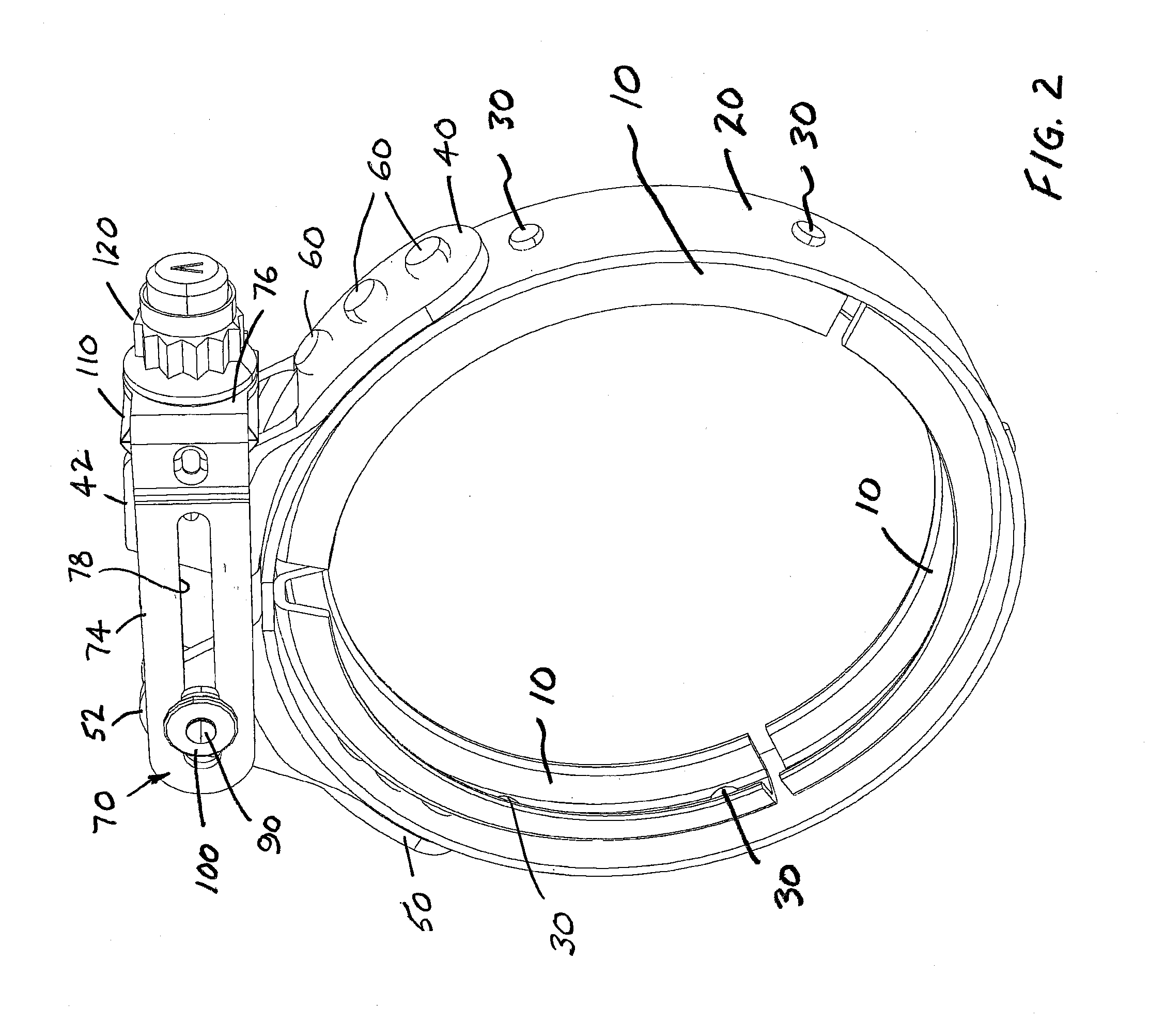
A hybrid sheet metal V-band coupling secures peripheral flanges at mating ends of first and second coupling members together. The coupling includes at least first and second V-retainers disposed in end-to-end relation for circumferential receipt over substantially 360 degrees of the peripheral flanges of the coupling members. A sheet metal member engages the V-retainers, and a latch assembly selectively secures the opposite ends of the sheet metal member. The sheet metal member is integrally joined to the V-retainers, for example, by welding or riveting. The latch assembly preferably includes ears formed from sheet metal that each include a first portion integrally secured (e.g., welded or riveted) to the sheet metal member and upturned second portions or lugs. The lugs preferably include embossments that extend outwardly therefrom.

Description

[0001]This application claims the priority benefit of U.S. provisional application Ser. No. 61 / 560,623, filed Nov. 16, 2012, the disclosure of which is expressly incorporated herein by reference.BACKGROUND[0002]The present disclosure relates to a coupling, and more particularly to what is referred to in the industry as a V-band coupling. More particularly, this disclosure relates to a more efficient way of manufacturing a coupling and resultant coupling which offers the flexibility of a sheet metal coupling with the robust design and enhanced features of a machined, rigid coupling.[0003]Both sheet metal and machined rigid couplings have numerous uses. Generally, these types of couplings are used to join together or couple peripheral flanges located at adjacent ends of a pair of tubular members. A retaining member is provided as a part of a clamping device for coupling the peripheral flanges of the tubular members.[0004]One problem with machined rigid couplings is the expense of labo...

Claims


Application Information

Patent Timeline
IPC IPC(8): F16L23/04
CPCF16L23/04Y10T29/49826Y10T29/49956F16L23/10
Inventor FRITSKEY, JOHN FRANKORZECH, JAMES MICHAEL
Owner VOSS INDS
Learn More