Estimating apparatus and estimating method
a technology of estimating apparatus and estimating method, which is applied in the direction of catheters, applications, therapy, etc., can solve the problems of inability to perform therapy reliably and accurately estimate the therapy process using laser catheters
- Summary
- Abstract
- Description
- Claims
- Application Information
AI Technical Summary
Benefits of technology
Problems solved by technology
Method used
Image
Examples
first embodiment
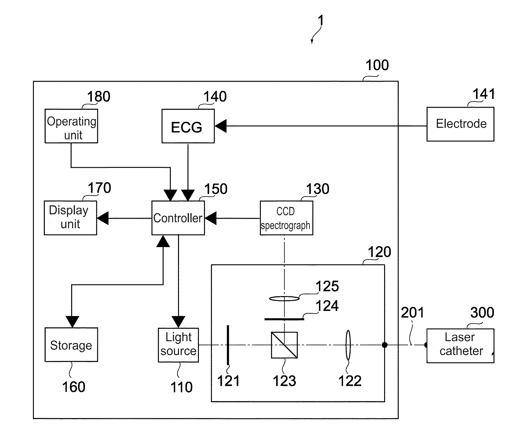
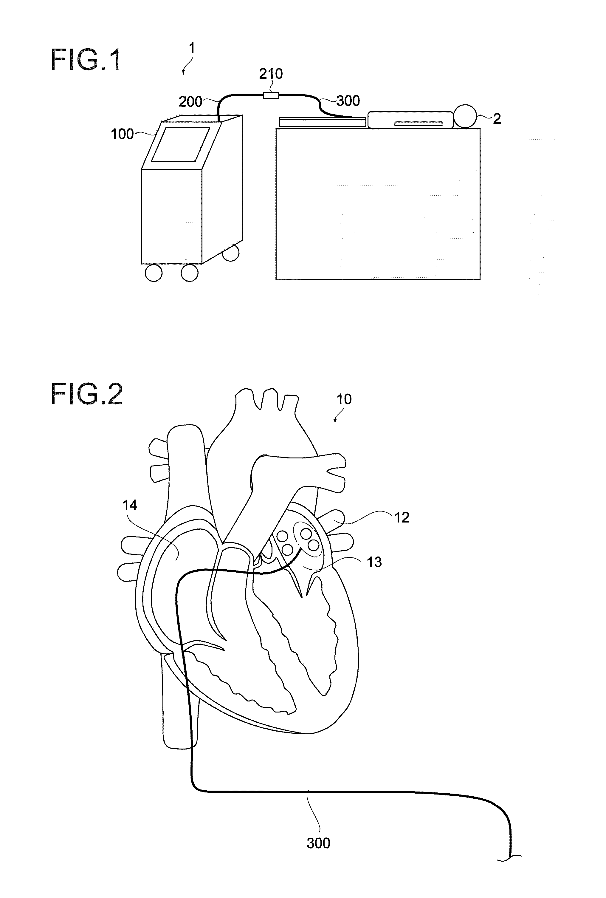
[0098]FIG. 1 is a schematic diagram showing a PDT apparatus according to a first embodiment of the present invention.
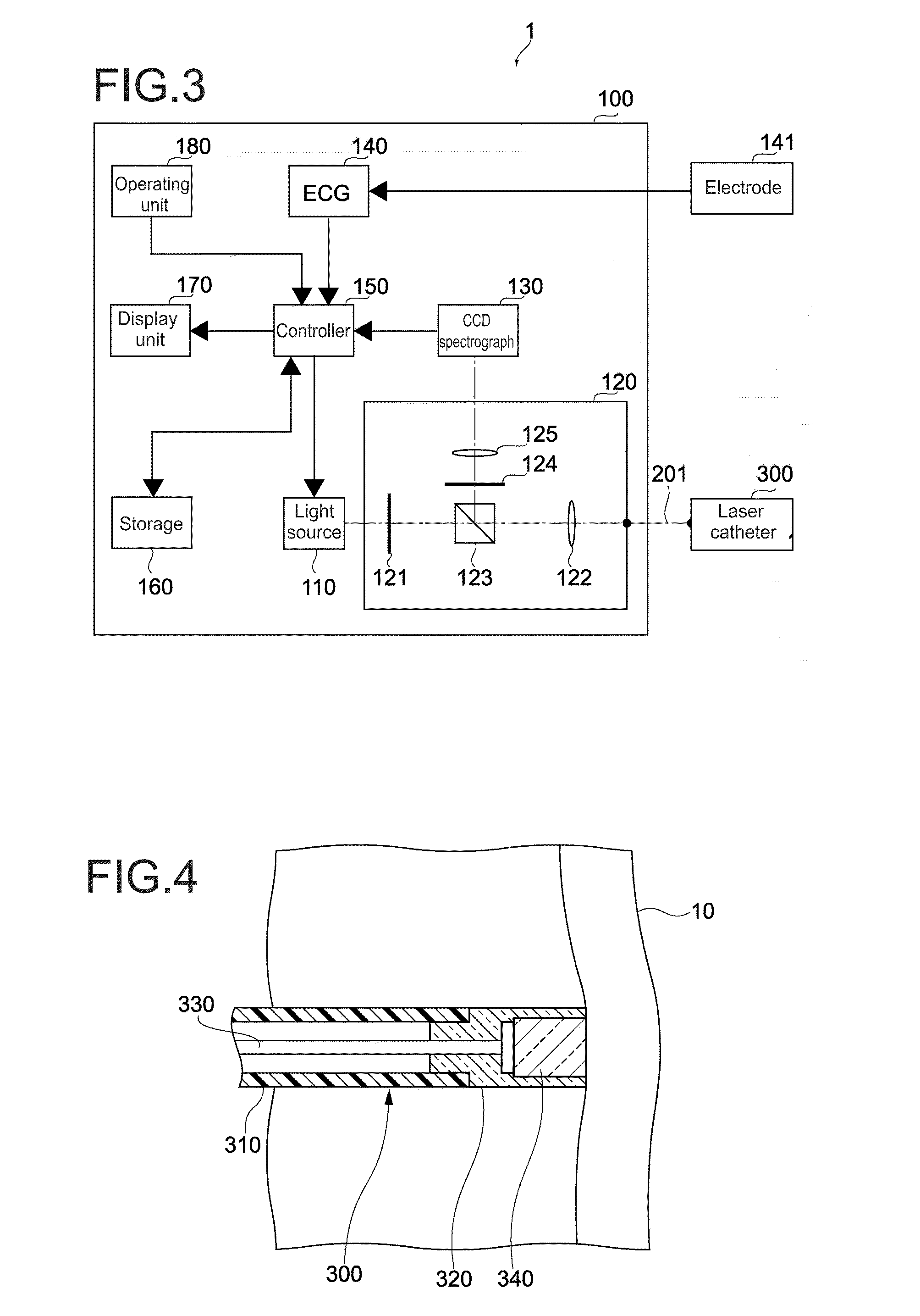
[0099]The PDT apparatus 1 includes a PDT apparatus main body 100, a tube 200 connected to the PDT apparatus main body 100, and a connector 210 provided on the end of the tube 200.
[0100]The tube 200 is a soft hollow tube, and is capable of transmitting light via an inner apparatus-attached optical fiber 201 (see FIG. 3.).
[0101]A laser the catheter 300 is detachably connected to the connector 210.
[0102]Photo-sensitive pharmaceutical is administered to a patient 2. In the case of being administered by intravenous injection, the administered photo-sensitive pharmaceutical diffuses in the blood, and then a tissue such as a cardiac-muscle tissue absorbs the pharmaceutical. A dose of photo-sensitive pharmaceutical necessary for therapy may be administered at one time by intravenous injection, may be administered continuously by intravenous drip, may be administered at one ti...
second embodiment
[0257]Next, a PDT apparatus according to another embodiment of the present invention will be described. In the following description, descriptions of configurations, functions, operations, and the like similar to those of the PDT apparatus 1 of the first embodiment will be omitted or simplified, and different points will mainly be described.
[0258]An optical system and a detection unit according to the second embodiment will be described.
[0259][Structures of optical system and detection unit]FIG. 17 is a block diagram showing an optical system, a detection unit, and the like of the second embodiment of the present invention.
[0260]An optical system 120a includes the short pass filter 121, the first lens 122, the PBS 123, a first dichroic mirror (hereinafter referred to as “DM”.) 126, and a second DM 127.
[0261]A detection unit 130a includes a first photodiode (hereinafter referred to as “PD”.) 131, and a second PD 132.
[0262]The first DM 126 reflects light having a certain wavelength ou...
third embodiment
[0269]In the third embodiment, the contact-monitoring steps are performed based on the phase difference between the peak of fluorescence intensity, which is in the interval between R-waves, and R-wave.
[0270]In the electric-conduction-block-formation determining operation of the first embodiment, it is determined that an electric-conduction block is formed based on the phase difference between the peak of fluorescence intensity, which is in the interval between R-waves, and R-wave. This principle may be applied to the contact-monitoring operation.
[0271]The light source 110 outputs the excitation light with the first intensity to the optical system 120. The detection unit 130 detects the fluorescence entered from the optical system 120. The detection unit 130 outputs the detected fluorescence intensity to the controller 150 as an electrical signal. The controller 150 calculates fluorescence intensity based on the obtained electrical signal.
[0272]Meanwhile, the electrocardiograph 140 o...
PUM
 Abstract
Description
Claims
Application Information
 - R&D
- Intellectual Property
- Life Sciences
- Materials
- Tech Scout
- Unparalleled Data Quality
- Higher Quality Content
- 60% Fewer Hallucinations
Browse by: Latest US Patents, China's latest patents, Technical Efficacy Thesaurus, Application Domain, Technology Topic, Popular Technical Reports.
© 2025 PatSnap. All rights reserved.Legal|Privacy policy|Modern Slavery Act Transparency Statement|Sitemap|About US| Contact US: help@patsnap.com


