
Support Mechanism for the Fluid End of a High Pressure Pump

a support mechanism and high-pressure pump technology, applied in the direction of machines/engines, liquid fuel engines, positive displacement liquid engines, etc., can solve the problems of high stress levels, time-consuming, down time and lost revenues, and simplify normal maintenance procedures , the effect of replacing the entire fluid end

Inactive Publication Date: 2013-05-09
FTS INT SERVICES
View PDF4 Cites 50 Cited by
  • Summary
  • Abstract
  • Description
  • Claims
  • Application Information

AI Technical Summary

Benefits of technology

The invention simplifies the support system for a fluid end by eliminating the need for stay rods. Instead, the fluid end is supported on a common frame using a mounting plate with a transversely extending slot and a complimentary slot in the base of the fluid end. A shear bar is positioned within the slot to absorb horizontal forces caused by the reciprocating plungers. Tensile studs extend from the fluid end and take up all the vertical loads placed on it. This design makes maintenance and replacement of the fluid end easier and eliminates the need for replacing the stay rods and nuts.

Problems solved by technology

This type of support is commonly referred to as a cantilever support and requires a large number of stay rods between the power end and the fluid end and creates high stress levels at the point where the stay rods are connected to the fluid end and the power end of the pump.
Due to the limited physical space due to the stay rods between the fluid end and the power end, this becomes a time consuming task.
Once again this is a time consuming task which results in down time and lost revenues.

Method used


Image

  • Support Mechanism for the Fluid End of a High Pressure Pump
  • Support Mechanism for the Fluid End of a High Pressure Pump
  • Support Mechanism for the Fluid End of a High Pressure Pump

Examples


Embodiment Construction

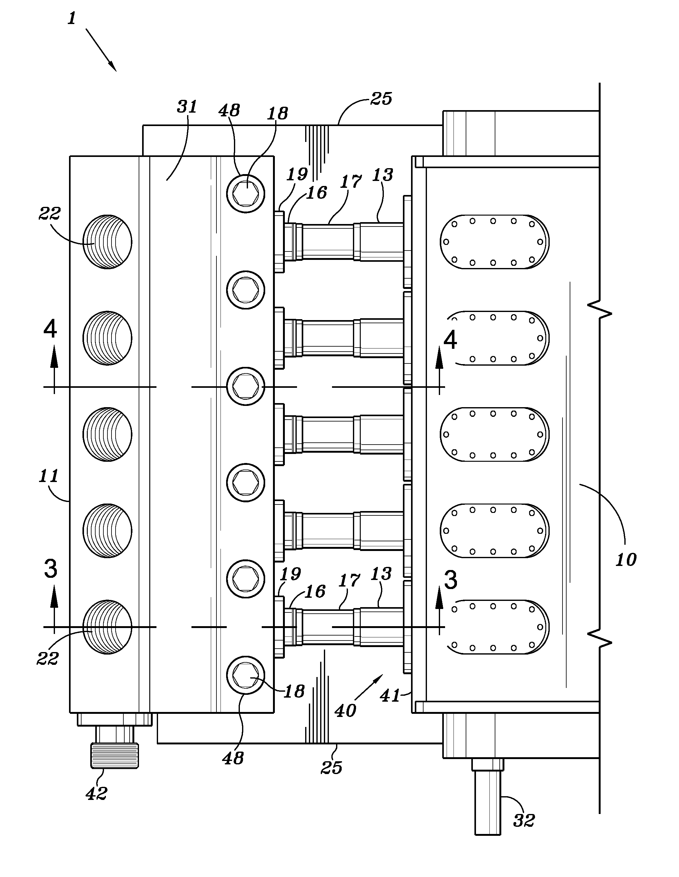
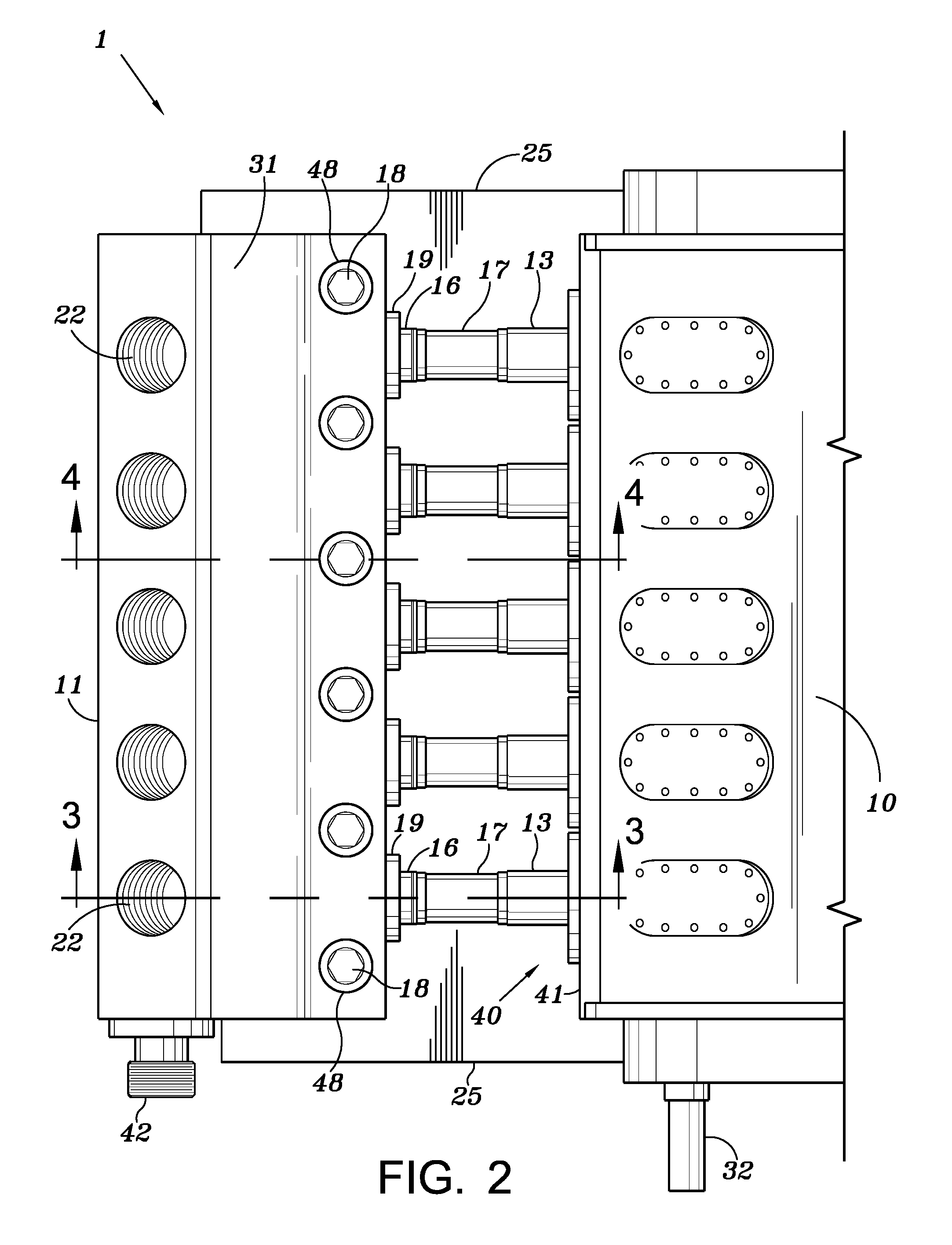
[0011]An embodiment of the invention is shown in FIGS. 2 and 3 and includes a fluid end 31 and a power end 40 which includes a drive input shaft 32. Fluid end 31 is formed from a solid block of stock material and is machined into the shape as shown in FIGS. 2 and 3. Fluid end 31 has a plurality of suction bores 24, outlet bores 22, and piston bores 45 formed therein as is shown in FIG. 2.

[0012]Fluid end 31 has a suction manifold attached to it similar to that shown at 51 in FIG. 1. Each outlet bore is in fluid communication with a transversely extending outlet passageway 25 for the high pressure fluid.

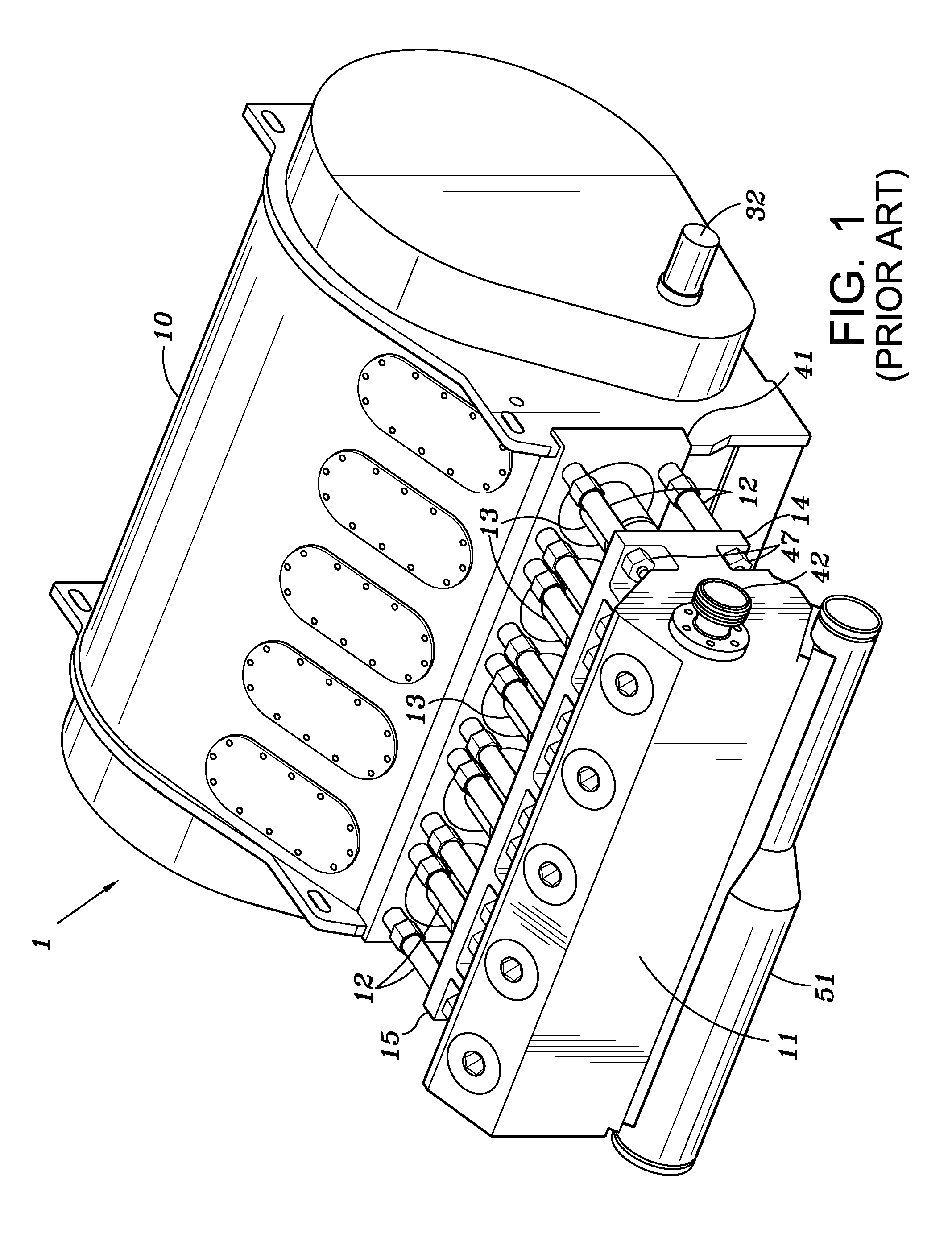
[0013]The fluid end includes a plurality of pump chambers, five of which are shown in FIG. 1. Referring to FIG. 3, an embodiment of the invention includes base support frame 25 for the pump. Power end 40 is supported on a first portion of the frame. At an opposite portion of the frame, a mounting plate 26 is secured to the support frame by any known means such as welding. Mounting plat...


PUM


Abstract

A fluid end for a high pressure pump is mounted to the power end in such a manner so as to allow free access to the plunger portion of the fluid end for maintenance or removal of the fluid end. The fluid end sits on a mounting plate which has a key slot. The lower surface of the fluid end also has a key slot and a shear bar is located within the slots. The fluid end further includes a plurality of tensile studs that secure the fluid end to the mounting plate which is secured to a support frame.

Description

BACKGROUND OF INVENTION[0001]1. Field of the Invention[0002]This invention relates to a high pressure pump which typically is composed of a fluid end and a power end. High pressure fluid pumps are used in many applications during the drilling and completion of an oil or gas well. One process called tracing normally utilizes several high pressure pumps in unison to inject a tracing fluid into the well in order to create small cracks or fractures in the formation to allow the oil and / or gas to escape from the formation.[0003]2. Description of Related Art[0004]The fluid end and power end of existing high pressure pumps are connected together in such a way that the fluid end is essentially supported in a cantilever fashion. FIG. 1 of the application discloses such an arrangement. Power end 10 of pump 1 is normally mounted on a frame or truck bed. A plurality of stay rods 12 extend outwardly from the power end and are secured to the fluid end 11 along upper and lower flanges 15 and 14. S...

Claims


Application Information

Patent Timeline
Patent Type & Authority Applications(United States)
IPC IPC(8): F04B19/22F04B23/00F16J10/02
CPCF04B1/0404F04B53/22F04B53/16
Inventor SMALL, TONY M.
Owner FTS INT SERVICES
Learn More