
Surgical Instrument Motor Pack Latch

a technology for surgical instruments and latches, applied in the direction of couplings, applications, forceps, etc., can solve the problems of increasing the cost of surgical instruments, and achieve the effect of preventing separation

Active Publication Date: 2013-05-02
INTUITIVE SURGICAL OPERATIONS INC
View PDF2 Cites 87 Cited by
  • Summary
  • Abstract
  • Description
  • Claims
  • Application Information

AI Technical Summary

Benefits of technology

The patent describes a mechanism that keeps two parts together when they are slidingly engaged with each other. The mechanism includes a latch shaft, a torsion spring, and a transverse latch member. When the parts are in a pre-engagement state, the latch shaft is in a certain position and the transverse latch member is oriented in a way that it interfers with the latch shaft. This prevents the parts from separating easily. When the parts move closer together, the latch shaft rotates to a position that allows the parts to easily move with each other. The latch shaft blocks the transverse latch member from moving in the opposite direction, keeping the parts in place. This mechanism is useful for keeping parts in a secure and easily engaged state.

Problems solved by technology

Such an actuation system, however, can include high cost drive train components, which increase the cost of the surgical instrument.

Method used


Image

  • Surgical Instrument Motor Pack Latch
  • Surgical Instrument Motor Pack Latch
  • Surgical Instrument Motor Pack Latch

Examples


Embodiment Construction

[0047]In the following description, various embodiments of the present invention will be described. For purposes of explanation, specific configurations and details are set forth in order to provide a thorough understanding of the embodiments. However, it will also be apparent to one skilled in the art that the present invention may be practiced without the specific details. Furthermore, well-known features may be omitted or simplified in order not to obscure the embodiment being described.

[0048]Minimally Invasive Robotic Surgery

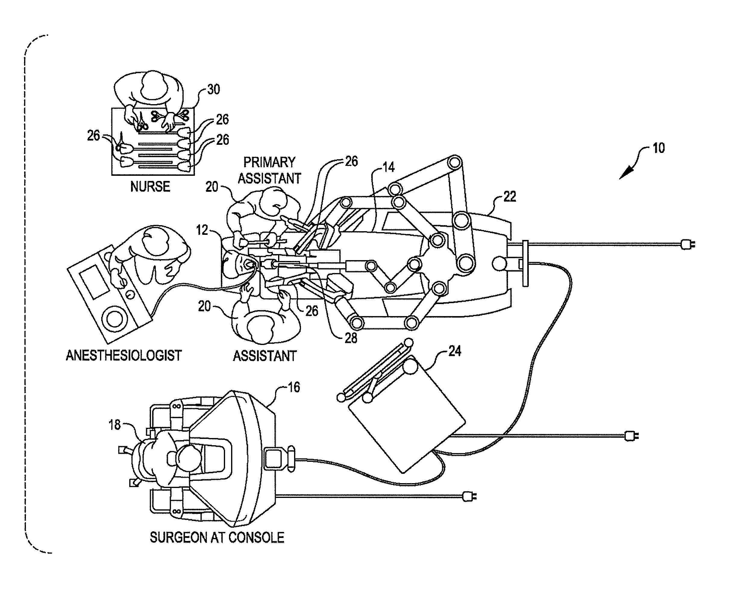
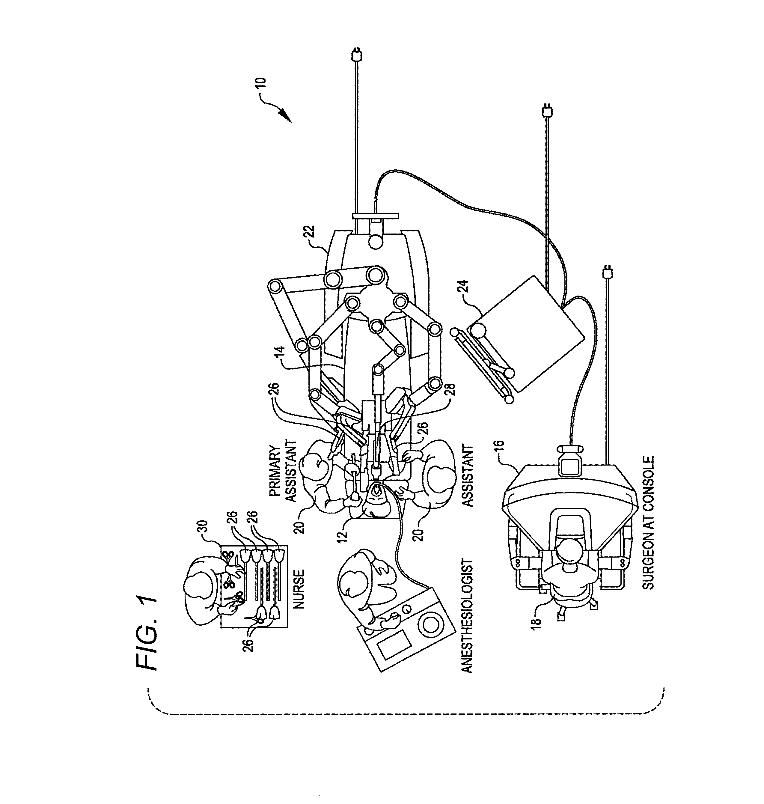
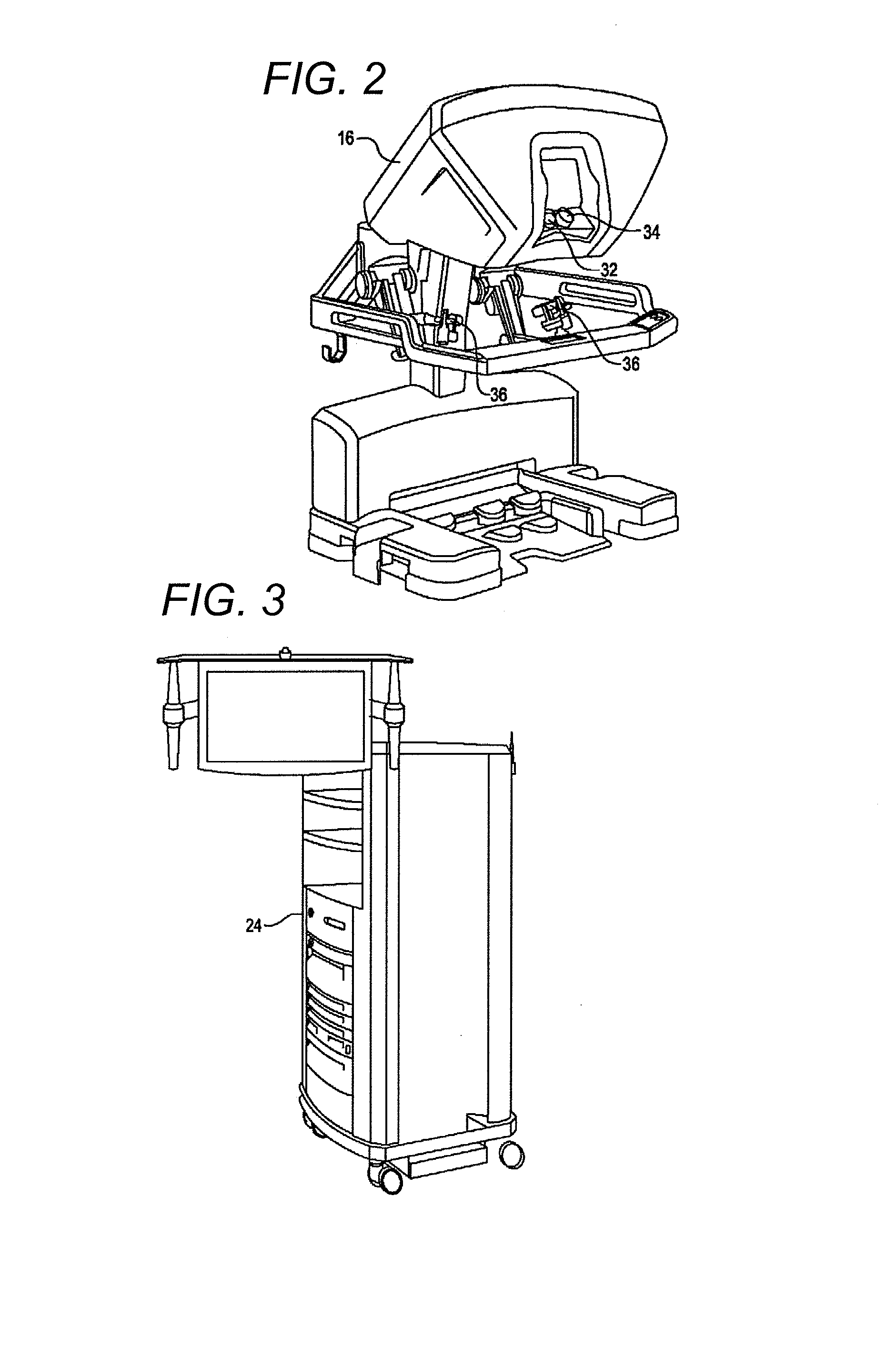
[0049]Referring now to the drawings, in which like reference numerals represent like parts throughout the several views, FIG. 1 is a plan view illustration of a Minimally Invasive Robotic Surgical (MIRS) system 10, typically used for performing a minimally invasive diagnostic or surgical procedure on a Patient 12 who is lying down on an Operating table 14. The system can include a Surgeon's Console 16 for use by a Surgeon 18 during the procedure. One or more...


PUM


Abstract

A latch mechanism selectively retains a first assembly to a second assembly. The first and second assemblies are configured for sliding engagement along an engagement axis. The latch mechanism includes a latch shaft mounted to the first assembly to rotate about a latch shaft axis, a torsion spring to bias the latch shaft relative to the first assembly, and a transverse latch member coupled with the second assembly. The latch mechanism is configured to automatically latch in response to the first assembly being pushed toward the second assembly. The transverse latch member interacts with the latch shaft to rotate the latch shaft in a first direction in response to movement of the first assembly toward the second assembly. Further motion of the first assembly toward the second assembly results in rotation of the latch shaft opposite to the first direction into a retention configuration that retains the transverse latch member.

Description

[0001]This application claims the benefit of U.S. Provisional Application No. 61 / 551,873, filed Oct. 26, 2011, and U.S. Provisional Application No. 61 / 560,203, filed Nov. 15, 2011, the entireties of which are incorporated by reference herein.BACKGROUND[0002]Minimally invasive surgical techniques are aimed at reducing the amount of extraneous tissue that is damaged during diagnostic or surgical procedures, thereby reducing patient recovery time, discomfort, and deleterious side effects. As a consequence, the average length of a hospital stay for standard surgery may be shortened significantly using minimally invasive surgical techniques. Also, patient recovery times, patient discomfort, surgical side effects, and time away from work may also be reduced with minimally invasive surgery.[0003]A common form of minimally invasive surgery is endoscopy, and a common form of endoscopy is laparoscopy, which is minimally invasive inspection and surgery inside the abdominal cavity. In standard ...

Claims


Application Information

Patent Timeline
IPC IPC(8): A61B19/00F16B21/00
CPCA61B2017/00477A61B2019/2223Y10T403/60A61B17/29A61B2019/2215A61B19/2203A61B2034/302A61B34/30A61B34/37
Inventor REID, ROBERT CYRUSZABINSKI, JOHN W.LOH, ALAN ETONSCHENA, BRUCE M.WEIR, DAVID W.DACHS, II, GREGORY W.BAILEY, DAVID W.WU, MELODY
Owner INTUITIVE SURGICAL OPERATIONS INC
Learn More